Perforated Corrugated Metal Ceiling
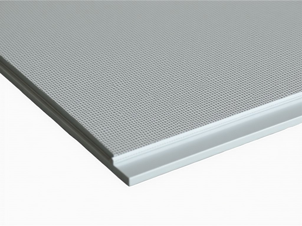
Perforated corrugated metal ceilings combine structural corrugation with engineered perforation patterns to deliver acoustic performance, airflow management, and aesthetic finish in industrial and
Perforated Corrugated Metal Ceiling
Perforated corrugated metal ceilings combine structural corrugation with engineered perforation patterns to deliver acoustic performance, airflow management, and aesthetic finish in industrial and commercial environments. The base material is typically cold-rolled steel, galvanized steel, or aluminum, formed into a sinusoidal or trapezoidal profile that increases rigidity while allowing for controlled perforation density. This configuration enables the ceiling to function as both a load-distributing panel and a sound-absorbing or ventilating surface, depending on perforation specifications.
Material Selection and Structural Properties
Material choice directly affects corrosion resistance, weight, and formability. Galvanized steel (Z275 coating) offers a balance of cost and durability for indoor industrial settings, while aluminum provides natural corrosion resistance and lower dead load, beneficial in retrofit applications where structural capacity is limited. Stainless steel grades (304, 316) are selected for high-humidity, chemical-exposed, or exterior environments. Base metal thickness typically ranges from 0.5 mm to 1.2 mm, with corrugation depth between 8 mm and 20 mm, determining moment of inertia and span capability.
The corrugated profile enhances stiffness perpendicular to the ribs, allowing spans up to 3.0 m between supports depending on gauge and profile geometry. Perforation does not significantly reduce structural integrity when open area remains below 25% and hole patterns are symmetrically distributed. Finite analysis shows that perforation primarily affects local buckling resistance rather than global bending capacity, provided the ligament between holes exceeds 1.5 times the hole diameter.
Perforation Patterns and Functional Performance
Perforation design governs acoustic absorption, airflow rate, and visual transparency. Common hole shapes include round, square, and slotted, arranged in staggered or linear grids. Open area percentage—calculated as the ratio of hole area to total panel area—typically ranges from 8% to 22% for acoustic applications and up to 35% for ventilation-focused designs. Hole diameters vary from 2 mm to 8 mm, with pitch (center-to-center distance) between 6 mm and 15 mm.
Acoustic performance is quantified by Noise Reduction Coefficient (NRC) and Sound Absorption Average (SAA). When backed by mineral wool or polyester insulation (25–50 mm thick, density 48–96 kg/m³), perforated corrugated panels achieve NRC values between 0.60 and 0.90, depending on open area and cavity depth. Airflow resistance follows Darcy’s law; pressure drop across the panel increases nonlinearly with open area reduction, making computational modeling essential for HVAC-integrated ceilings.
Manufacturing Process and Dimensional Control
Production begins with coil-fed roll forming, where the metal strip passes through a series of rollers to establish the corrugated profile. Perforation occurs either pre-forming (on flat sheet) or post-forming, depending on hole shape and tooling constraints. Pre-forming allows higher perforation speeds and complex patterns but requires careful management of springback and profile distortion. Post-forming preserves dimensional accuracy but may limit hole geometry due to roll-forming station interference.
Tolerances are maintained per ASTM E1657 for roll-formed products: profile height ±0.5 mm, pitch ±2 mm per meter, and length ±3 mm. Perforation registration is controlled to ±0.3 mm relative to panel edges. Surface treatments—such as galvanizing, powder coating (60–80 µm thickness), or PVDF fluoropolymer finish—are applied after forming to ensure complete coverage of cut edges and perforations.
Applications in Industrial and Commercial Environments
In manufacturing facilities, these ceilings manage reverberation from machinery while permitting upward exhaust of warm air through perforations, improving thermal stratification without compromising acoustic control. In data centers, specific perforation patterns support directed airflow from raised floors to server inlets when integrated with plenum systems, balancing cooling efficiency with noise suppression from CRAC units.
Transportation hubs such as airports and train stations use perforated corrugated ceilings for their durability under cyclic loading, ease of panel replacement, and compatibility with integrated lighting and signage systems. The open area facilitates smoke dispersion and sensor accessibility in fire safety designs. In food processing plants, stainless steel variants with smooth, cleanable finishes meet hygiene standards while resisting washdown corrosion.
Customization Options and Project Integration
Panel length is customizable up to 6.0 m limited by transportation and handling constraints. Width typically ranges from 200 mm to 600 mm (cover width), determined by corrugation pitch and structural requirements. End treatments include square cut, rolled edge, or flange for overlap jointing. Perimeter trims and transition components are fabricated to match profile and finish.
Perforation zones can be varied across a single panel—for example, higher open area near diffusers or return grilles, and lower open area along perimeter for acoustic buffering. Custom logos, gradients, or alphanumeric patterns are achievable via laser perforation or specialized tooling, subject to minimum ligament constraints. Insulation backing is supplied as loose-fill in bags or laminated facings, with options for fire-retardant (ASTM E84 Class A) or moisture-resistant facings.
Quality Control and Testing Protocols
Dimensional verification occurs at each stage: incoming coil thickness (micrometer), post-forming profile (laser scanner or template gauge), and perforation alignment (vision system). Coating thickness is measured via magnetic induction or XRF, with adhesion tested per ASTM D3359. Acoustic performance is validated in reverberation chambers per ASTM C423, with results correlated to open area and backing material.
Structural capacity is assessed through three-point bending tests on full-width samples, comparing deflection against theoretical models. For projects requiring certified load data, finite element analysis reports are available upon request. Visual inspection checks for scratches, coating uniformity, and perforation burrs, with acceptance criteria based on viewing distance and lighting conditions (e.g., 500 lux, 1.5 m distance).
| Property | Typical Range | Notes |
|---|---|---|
| Base Metal Thickness | 0.5 – 1.2 mm | Depends on material and span requirements |
| Corrugation Depth | 8 – 20 mm | Affects stiffness and span capability |
| Open Area Percentage | 8 – 35% | Application-dependent; acoustic vs. ventilation |
| Hole Diameter | 2 – 8 mm | Influences acoustic frequency response |
| Panel Width (Cover) | 200 – 600 mm | Determined by profile and installation method |
| Maximum Length | 6.0 m | Limited by logistics and handling |
| NRC (with 50 mm insulation) | 0.60 – 0.90 | Varies with open area and cavity depth |
Installation Considerations
Installation typically involves mechanical fastening to structural supports using screws, clips, or suspension systems. For concealed fastener systems, panels engage via interlocking edges or pressure plates attached to studs or purlins spaced at 600 mm or 1200 mm intervals. Thermal expansion must be accommodated—steel expands approximately 12 µm/m·°C—requiring slip joints or elongated holes in long runs to prevent buckling or fastener fatigue.
Access panels are integrated using matching perforated or solid frames, allowing maintenance of plenums, lighting, or HVAC components. Edge clearance between panels and walls is typically 10–20 mm to accommodate drift and finishing trim. In seismic zones, attachment details follow ASCE 7 requirements for suspended ceilings, including bracing wires and compression struts where applicable.
Environmental and Lifecycle Factors
Steel and aluminum panels are 100% recyclable at end of life, with scrap value recovering a portion of initial cost. Coatings are selected for longevity—PVDF finishes exceed 20 years in UV exposure without significant chalking or fading. Maintenance involves periodic cleaning with neutral pH detergents; abrasive tools should be avoided to preserve coating integrity. In indoor environments, the ceiling contributes to thermal mass when installed over plenums, moderating temperature swings.
Embodied carbon varies by material: recycled aluminum has lower embodied energy than virgin steel, while galvanized steel benefits from established recycling streams. Environmental Product Declarations (EPDs) are available upon request for specific material and coating combinations. The long service life and low maintenance reduce lifetime environmental impact compared to suspended tile systems requiring frequent replacement.
For project-specific configuration, including perforation design, material selection, and acoustic modeling, contact our technical team to discuss requirements and obtain submittal drawings.

More Products

Send Inquiry
If you are interested in our products, leave your information here and we will be in touch shortly.