Perforated Metal Panel Manufacturers
Perforated metal panels are engineered components designed to provide controlled airflow, light transmission, acoustic management, and structural support across industrial, architectural, and
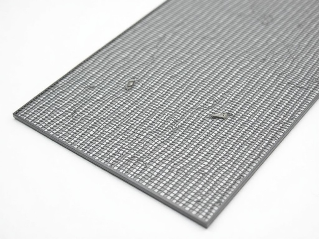
Perforated Metal Panel Manufacturers: Technical Overview
Perforated metal panels are engineered components designed to provide controlled airflow, light transmission, acoustic management, and structural support across industrial, architectural, and mechanical systems. Manufacturers produce these panels by precision-punching or laser-cutting repeating patterns of holes into sheet metal substrates, tailoring open area, hole geometry, and layout to meet specific functional requirements. The selection of material, perforation pattern, and panel dimensions directly influences performance characteristics such as pressure drop, sound attenuation, structural rigidity, and corrosion resistance. Industrial buyers evaluate manufacturers based on their ability to deliver consistent tolerances, material traceability, and scalable production without compromising design intent.
Material Selection and Mechanical Properties
Common substrate materials include carbon steel (ASTM A1008/A1018), galvanized steel (ASTM A653), stainless steel (grades 304, 316L), aluminum (3003-H14, 5052-H32), and corten steel. Each material offers distinct trade-offs: carbon steel provides high tensile strength (typically 300–550 MPa) but requires coating for corrosion resistance; stainless steel maintains strength at elevated temperatures and resists chemical attack; aluminum offers a strength-to-weight ratio advantageous in weight-sensitive applications; corten steel develops a stable patina that eliminates the need for painting in outdoor environments. Material thickness typically ranges from 0.5 mm to 6.0 mm, with thicker gauges used for structural panels and thinner gauges for decorative or filtration applications.
Hole shapes—round, square, slotted, hexagonal, or custom geometries—are selected based on flow dynamics, particle retention, or aesthetic goals. Round holes are most common due to predictable flow characteristics and ease of tooling; slotted holes provide higher open area in linear arrangements for directional airflow; hexagonal patterns maximize open area while maintaining ligament strength. The ligament width (material between holes) must be sufficient to prevent tearing under load; minimum ligament width is typically 1.0 mm for carbon steel and 0.8 mm for aluminum to avoid premature failure during forming or installation.
Perforation Patterns and Open Area Calculations
Open area percentage—the ratio of hole area to total panel area—is a critical design parameter affecting airflow, light transmission, and acoustic performance. For round holes on a staggered 60° pattern, open area is calculated as (π × d²) / (2 × s² × √3) × 100%, where d is hole diameter and s is center-to-center spacing. A 10 mm diameter hole on a 15 mm staggered pitch yields approximately 38% open area. Square holes on a straight grid use (d² / s²) × 100%, while slotted holes require more complex integration of length and width. Manufacturers provide open area charts for standard patterns, but custom layouts require flow simulation or empirical testing to validate performance under expected pressure differentials.
Pattern orientation affects structural behavior: staggered arrangements distribute load more evenly than straight rows, reducing stress concentration at hole edges. For panels subjected to wind load or mechanical vibration, finite element analysis is often used to verify that ligament sections remain below yield strength. Edge margins—typically 10–20 mm unperforated border—are maintained to facilitate framing, welding, or fastening without compromising hole integrity near the perimeter.
Manufacturing Processes and Tolerance Control
Perforation is achieved via CNC turret punches, progressive dies, or fiber laser systems. Turret punching offers high speed for repetitive patterns in thin-to-medium gauges (up to 3 mm), with positional accuracy typically ±0.1 mm. Laser cutting enables complex geometries and variable hole sizes without tooling changes, ideal for prototyping or low-volume custom orders, though heat-affected zones may require post-processing in heat-sensitive alloys. Progressive dies are used for high-volume production of identical panels, achieving tolerances of ±0.05 mm in hole location and ±0.02 mm in hole diameter when tooling is well-maintained.
Post-perforation operations include leveling, deburring, and surface treatment. Leveling corrects residual stress-induced warping, particularly important in thin gauges where hole removal creates imbalance. Deburring removes sharp edges formed during punching, critical for safety in handling and to prevent particle entrapment in filtration applications. Surface treatments—such as powder coating, anodizing (for aluminum), passivation (for stainless steel), or galvanic coating—are applied after perforation to ensure uniform coverage and prevent corrosion initiation at hole edges.
Industrial Applications and Functional Rationale
In HVAC systems, perforated panels serve as diffuser faces where open area and hole distribution determine air throw, noise reduction, and mixing efficiency. A 40–50% open area with 3–5 mm round holes is typical for ceiling diffusers, balancing airflow velocity with pressure drop (<25 Pa at 2.5 m/s). In acoustic enclosures, panels act as porous absorbers; hole size and backing cavity depth are tuned to target specific frequency ranges (e.g., 5–10 mm holes with 50 mm mineral wool backing absorb mid-frequency noise between 250–1000 Hz). For machine guarding, panels provide visibility and containment while maintaining structural integrity; hole size is limited to <6 mm to prevent finger ingress per ISO 13857, with open area kept below 40% to ensure adequate impact resistance.
In industrial filtration, perforated panels support filter media or act as standalone screens. Hole size is selected to prevent media blow-through while minimizing pressure drop; for pleated cartridge filters, 0.8–1.2 mm holes are common in stainless steel tubes. In architectural facades, perforated metal provides solar shading; hole pattern and density are calculated using sun path analysis to block summer sun while allowing winter penetration, reducing cooling loads by 15–30% in climates with high solar gain. In food processing, panels are used in drying trays and washing systems where 316L stainless steel with 2–3 mm holes ensures drainage, cleanability, and resistance to chloride-induced pitting.
Quality Control and Inspection Protocols
Dimensional inspection verifies hole diameter, spacing, and overall panel flatness using coordinate measuring machines (CMM) or optical comparators. Hole diameter tolerance is typically ±0.1 mm for punched holes and ±0.05 mm for laser-cut features. Flatness is measured as deviation from a reference plane; architectural panels often require <3 mm deviation over 1200 mm length to prevent visual distortion, while industrial screens may tolerate up to 6 mm. Open area is validated via optical scanning or gravimetric methods—measuring mass loss after acid etching of a sample—to confirm theoretical calculations match actual output.
Material test reports (MTRs) are supplied for each coil or sheet lot, confirming chemical composition and mechanical properties. Visual inspection under 500 lux lighting checks for burrs, mis-holes, roller marks, or coating defects. For applications requiring hygiene compliance (e.g., food, pharmaceutical), surface roughness is measured (Ra < 0.8 µm) and crevice sites are evaluated for cleanability. Packaging includes polyethylene wrapping and edge protectors to prevent abrasion during transit; panels are stacked flat or on edge with interstitial spacers to avoid hole deformation.
Customization and Engineering Support
Manufacturers offer engineering consultation to translate performance requirements into manufacturable specifications. Clients provide target open area, pressure drop limits, acoustic absorption coefficients, or visual transparency goals; engineers reverse-engineer hole size, spacing, pattern, and material thickness using empirical data or simulation tools. Prototypes are produced via laser cutting for rapid validation before committing to hard tooling. For large projects, manufacturers provide installation drawings showing mounting methods, expansion joint allowances, and sealing details to accommodate thermal movement.
Customization extends to secondary operations: bending, rolling, welding, or inserting reinforcing stiffeners. Panels can be formed into cylinders, cones, or complex curves using press brakes or slip rolls, with perforation integrity maintained if bend radius exceeds 2× material thickness. Welding is performed on unperforated edges or via plug welds in ligament areas to avoid weakening hole margins. Some manufacturers integrate perforated panels into larger assemblies—such as door cores, ceiling tiles, or equipment housings—providing a single-source solution that reduces supplier coordination risk.
Typical Perforated Metal Panel Specifications
| Parameter | Typical Range / Options |
|---|---|
| Material Thickness | 0.5 mm – 6.0 mm (custom gauges available) |
| Hole Diameter | 0.8 mm – 50.0 mm (round); slotted and custom shapes per drawing |
| Center-to-Center Spacing | 1.5 mm – 100.0 mm (dependent on hole size and material) |
| Open Area Percentage | 5% – 70% (limited by structural integrity and manufacturing constraints) |
| Standard Sheet Sizes | 1000×2000 mm, 1250×2500 mm, 1500×3000 mm (custom lengths available) |
| Surface Finish | Mill finish, galvanized, powder coated (RAL colors), anodized, passivated, brushed |
*Values represent common industrial offerings. Exact specifications are customizable according to project requirements, material availability, and tooling constraints.
Selecting a perforated metal panel manufacturer requires evaluation of technical capability beyond basic fabrication. Key considerations include in-house tooling design, material certification traceability, process control for hole consistency, and experience with post-perforation forming and finishing. Manufacturers that provide engineering support—such as CFD analysis for airflow prediction, acoustic modeling for noise control, or FEA for structural validation—reduce project risk by identifying performance gaps early. Long-term value is derived from dimensional stability, corrosion resistance, and consistent performance over the product lifecycle, not merely initial cost.
For project-specific requirements, including custom hole patterns, material certifications, or integration into larger assemblies, contact the manufacturer’s engineering team to discuss application needs, provide performance targets, and request a feasibility review. Detailed specifications, including hole layout drawings, material data sheets, and lead time estimates, are available upon request following technical consultation.

More Products

Send Inquiry
If you are interested in our products, leave your information here and we will be in touch shortly.