Perforated Metal Screen Panels
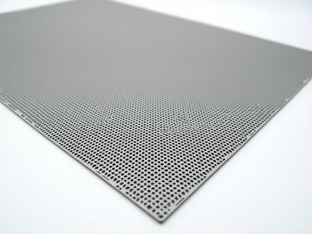
Perforated metal screen panels are engineered components formed by punching precise hole patterns into sheet metal substrates. These panels serve functional roles in filtration, ventilation,
Perforated Metal Screen Panels
Perforated metal screen panels are engineered components formed by punching precise hole patterns into sheet metal substrates. These panels serve functional roles in filtration, ventilation, shielding, and separation across industrial environments. The perforation process creates open areas that allow controlled passage of air, light, sound, or fluids while maintaining structural integrity. Panel performance depends on hole geometry, material thickness, open area percentage, and edge treatment. Selection requires matching these parameters to specific process demands such as pressure drop, particle retention, or electromagnetic shielding effectiveness.
Material Selection and Substrate Properties
Common substrate materials include carbon steel, stainless steel (grades 304, 316L), aluminum alloys (3003, 5052), and galvanized steel. Material choice influences corrosion resistance, strength-to-weight ratio, thermal conductivity, and magnetic properties. For example, 316L stainless steel offers superior resistance to chlorides and acidic environments compared to 304, making it suitable for chemical processing or marine applications. Aluminum provides lightweight characteristics with good thermal dissipation, often used in HVAC or aerospace ductwork. Carbon steel is selected when cost and magnetic permeability are priorities, provided surface treatment mitigates oxidation.
Substrate thickness typically ranges from 0.5 mm to 6.0 mm, affecting panel rigidity and load-bearing capacity. Thicker gauges resist deformation under pressure differentials but increase weight and tooling wear during perforation. Thinner materials allow higher open areas but may require additional framing or stiffening to prevent buckling. The relationship between thickness, hole size, and pitch determines the panel’s structural limits under operational stress.
Perforation Patterns and Open Area Characteristics
Hole shapes include round, square, slotted, hexagonal, and custom geometries. Round holes are most common due to predictable flow dynamics and ease of tooling. Slot orientations (longitudinal or transverse) influence directional flow resistance and particle capture efficiency. Open area percentage—the ratio of hole area to total panel area—directly impacts airflow, light transmission, and pressure drop. Typical open areas range from 15% to 60%, depending on hole size and spacing.
Pitch (center-to-center distance between holes) and hole diameter define the pattern’s density. A smaller pitch with larger holes increases open area but reduces ligament strength between holes. Conversely, larger pitch with smaller holes enhances mechanical stability but reduces flow capacity. Engineers balance these factors based on application needs: high open area for low-pressure-drop filtration, smaller holes for fine particle retention, or specific patterns for acoustic damping or electromagnetic interference (EMI) shielding.
Manufacturing Considerations and Tolerances
Perforation is typically achieved via CNC turret punches, rotary dies, or laser systems. Turret punching offers high throughput for standard patterns with tolerances of ±0.1 mm on hole position and ±0.05 mm on diameter. Laser perforation enables complex geometries and variable hole sizes but is slower and more costly. Rotary die punching suits high-volume production of repetitive patterns with consistent edge quality.
Post-perforation processes include deburring, leveling, and edge finishing. Burrs generated during punching can affect fluid flow or cause abrasion in moving-part applications; these are removed via tumbling, brushing, or electrochemical deburring. Leveling corrects distortion introduced during perforation, ensuring flatness within specified tolerances (e.g., ≤3 mm/m). Edge treatments—such as folding, framing, or welding to support structures—prevent unraveling and facilitate installation.
Industrial Applications and Functional Rationale
In HVAC systems, perforated panels serve as diffuser faces or return air grilles where controlled airflow distribution and noise reduction are critical. The hole pattern breaks up laminar flow, promoting mixing and reducing turbulence-induced noise. In industrial filtration, panels act as pre-filters or support media for filter cartridges, where open area minimizes pressure drop while retaining larger particulates. The material and hole size are selected based on the contaminant type and required service life.
Perforated panels are used in machine guarding to provide visibility and ventilation while maintaining safety barriers. Hole size is constrained by safety standards (e.g., ISO 13857) to prevent finger or tool penetration. In architectural applications, panels function as sunshades or facades where perforation density controls solar gain and visual permeability. Electromagnetic shielding applications rely on conductive materials with hole sizes significantly smaller than the wavelength of target frequencies to attenuate EMI/RFI.
Customization Options and Design Flexibility
Panel dimensions are customizable to fit specific equipment enclosures, ductwork, or architectural openings. Standard widths often align with common sheet sizes (e.g., 1000 mm, 1250 mm, 1500 mm) to minimize scrap, but non-standard dimensions are available upon request. Lengths can exceed 3000 mm with appropriate support to prevent sag. Hole patterns can be varied across the panel surface—such as graduated open area for airflow balancing or zoned configurations for multi-stage filtration.
Surface treatments include powder coating, anodizing (for aluminum), passivation (for stainless steel), and galvanizing. These enhance corrosion resistance, improve aesthetics, or provide electrical insulation. Coating thickness and adhesion are controlled to avoid filling perforations. For applications requiring electrical grounding or conductivity, coatings are selected to maintain surface continuity.
Additional features such as hinges, latches, gaskets, or mounting flanges can be integrated during fabrication. These facilitate access for maintenance, ensure sealing in pressurized systems, or simplify assembly. Design for manufacturability (DFM) principles are applied to minimize tooling changes and assembly steps.
Quality Control and Inspection Protocols
Dimensional verification includes hole diameter, pitch, open area, panel flatness, and squareness. Optical comparators, coordinate measuring machines (CMMs), or automated vision systems assess hole consistency across the panel surface. Open area is calculated from scanned images or pressure drop measurements to confirm design intent.
Material certification (e.g., mill test reports) validates alloy composition and mechanical properties. Visual inspection identifies surface defects, burrs, or coating imperfections. For critical applications, non-destructive testing such as dye penetrant or ultrasonic testing may be specified to detect subsurface flaws. Acceptance criteria are defined in accordance with industry standards or customer specifications.
Packaging and Logistics Considerations
Panels are packaged to prevent deformation, scratching, or corrosion during transit. Common methods include flat stacking with interleaving paper or plastic film, vertical bundling with edge protectors, or custom crating for oversized units. Humidity-controlled packaging is used for corrosion-sensitive materials. Each package includes labeling with part number, material grade, perforation pattern, and quantity.
For export shipments, packaging adheres to ISPM 15 standards for wood pallets and includes moisture barriers and desiccants. Shock and tilt indicators may be added to monitor handling conditions. Documentation includes material safety data sheets (MSDS), mill certificates, and inspection reports as required.
| Parameter | Typical Range / Options | Notes |
|---|---|---|
| Material Thickness | 0.5 mm – 6.0 mm | Affects rigidity and open area limits |
| Hole Diameter (Round) | 0.8 mm – 20 mm | Smaller holes increase flow resistance |
| Open Area Percentage | 15% – 60% | Depends on hole size and pitch |
| Standard Widths | 1000 mm, 1250 mm, 1500 mm | Custom widths available |
| Surface Treatment | Powder coat, anodize, passivate, galvanize | Selected per environment |
For technical consultation, dimensional validation, or quotation requests, contact our engineering team to discuss your specific application requirements. Provide details on operating conditions, material compatibility, hole pattern preferences, and required tolerances to ensure accurate specification.
More Products

Send Inquiry
If you are interested in our products, leave your information here and we will be in touch shortly.