Perforated Metal Sheet Ceiling
Perforated metal sheet ceilings serve as both architectural finishes and functional acoustic or ventilation elements. The pattern of holes allows controlled air passage, sound diffusion, or light
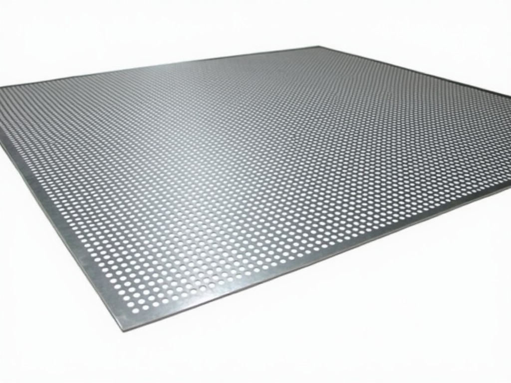
Perforated Metal Sheet Ceiling
Function and Design Principles
Perforated metal sheet ceilings serve as both architectural finishes and functional acoustic or ventilation elements. The pattern of holes allows controlled air passage, sound diffusion, or light transmission while maintaining structural integrity. Hole size, shape, spacing, and open area percentage are engineered to meet specific environmental performance targets.
Unlike solid ceilings, perforated systems interact with the plenum space above, enabling integration with HVAC, lighting, or fire suppression systems. The metal substrate provides durability, fire resistance, and dimensional stability under varying humidity and temperature conditions.
Design begins with defining the required open area (typically 15%–40%) based on airflow or acoustic needs. Hole geometry—round, square, slot, or custom—is selected to balance visual appearance with functional performance. Edge treatments and suspension methods are then engineered to ensure long-term flatness and safety.
Material Selection and Properties
Common materials include aluminum alloys (3003, 5052), galvanized steel (DX51D+Z), and stainless steel (304, 316). Aluminum offers low density (~2.7 g/cm³) and natural corrosion resistance, suitable for interior and moderate exterior use. Galvanized steel provides higher strength and cost efficiency for large-span installations in dry environments.
Stainless steel grades are selected for environments requiring resistance to moisture, chemicals, or frequent cleaning—such as food processing, pharmaceutical, or marine-adjacent facilities. Thickness typically ranges from 0.5 mm to 1.5 mm, depending on span, hole size, and load requirements. Thinner gauges reduce weight but may require closer support spacing to prevent deflection.
Surface treatments include mill finish, anodizing (for aluminum), powder coating (RAL colors), or PVDF coatings for enhanced UV and chemical resistance. Coating thickness and adhesion are controlled to meet architectural durability standards without clogging perforations.
Perforation Patterns and Open Area Calculation
Open area percentage is calculated as the ratio of hole area to total sheet area, directly affecting airflow, sound absorption, and light transmission. For round holes: Open Area (%) = (π × d² ÷ 4) ÷ (p²) × 100, where d = hole diameter and p = pitch (center-to-center distance).
Square holes use: Open Area (%) = (a² ÷ p²) × 100, with a = side length. Slot perforations require custom calculation based on length, width, and staggered or aligned layout. Typical open areas range from 18% for acoustic control to 35%+ for plenums requiring high airflow.
Pattern regularity affects both performance and aesthetics. Staggered (60°) layouts offer higher open area at equal pitch compared to aligned grids. Hole edge quality—burr-free, clean-cut—is critical to prevent air turbulence, sound reflection, or coating damage during fabrication.
Acoustic and Airflow Performance
When backed by an absorbent material (e.g., mineral wool or foam), perforated ceilings act as Helmholtz resonators. The hole size, panel thickness, and cavity depth determine the resonant frequency, enabling targeted absorption in mid-frequency ranges (500–2000 Hz) common in speech and machinery noise.
Airflow resistance is characterized by pressure drop across the sheet at given velocity. Lower open area increases resistance; designers use perforated sheets to create uniform plenum pressure or to diffuse air without drafts. Computational fluid dynamics (CFD) is often used to validate performance in large installations.
Combined acoustic and airflow performance is evaluated using ASTM C423 (sound absorption) and AMCA 500 (airflow resistance) test methods. Results are project-specific; typical NRC values range from 0.60 to 0.90 with appropriate backing, depending on perforation design and cavity depth.
Structural Considerations and Installation
Deflection under self-weight and incidental loads is limited to L/360 or L/240 depending on application. Support spacing is determined by material thickness, hole size, and span—typically 600 mm to 1200 mm for aluminum, up to 1500 mm for steel. Perforations reduce effective cross-section, requiring increased gauge or closer supports compared to solid sheets.
Installation methods include concealed T-grid systems, direct screw fixation to substrates, or suspended wire/hanger assemblies. Edge profiles (folded, flanged, or extruded) provide rigidity and alignment. Accessibility for maintenance is achieved through removable panels or hinged sections in critical zones.
Thermal expansion is accommodated via slotted holes or floating connections, particularly in long runs or environments with temperature cycling. Fire performance is rated per ASTM E84 or EN 13501-1; perforated metal sheets typically achieve Class A (non-combustible) or B-s2,d0 ratings based on substrate and coating.
Customization Options
Perforated metal ceilings are highly adaptable to project-specific requirements. Hole patterns can be customized to include logos, gradients, or variable density zones for wayfinding or acoustic zoning. Material, thickness, finish, and edge treatment are selected based on environmental exposure, load, and aesthetic goals.
Panel dimensions are typically limited by material width (max 1250 mm for coils) and handling constraints. Lengths up to 3000 mm are common; longer spans require intermediate supports or roll-formed profiles. Curved or tapered panels are available upon request, requiring specialized forming tools and validation.
Integration with accessories—such as light fixtures, diffusers, or access panels—is coordinated during design. CAD models and shop drawings are provided to ensure compatibility with MEP systems. All customizations are subject to manufacturability review to avoid tooling delays or cost overruns.
Quality Control and Testing
Quality control begins with material certification (mill test reports) and continues through each production stage. Hole dimensions are verified using optical comparators or CMM sampling to ensure positional accuracy and diameter consistency. Open area is validated per batch using image analysis or flow bench testing.
Flatness is measured using laser profilometers or straightedge/gap methods, with tolerances typically ≤1.5 mm per meter. Coating thickness and adhesion are tested per ASTM D7091 and D3359. Visual inspection checks for scratches, dents, or coating defects under standardized lighting.
Final inspection includes dimensional verification, squareness, and edge quality. Packaging is designed to prevent bending or surface damage during transit. Test reports and compliance documentation are available upon request for project submission.
Typical Applications
Perforated metal sheet ceilings are used in environments where durability, hygiene, and performance must coexist. In transportation hubs (airports, train stations), they provide long-lasting finishes that resist impact and allow plenum access for wiring and ducting. Their non-combustible nature meets strict fire safety codes in public assembly spaces.
In healthcare facilities, they support cleanable surfaces and contribute to noise reduction in corridors and waiting areas. The ability to integrate HEPA-filtered plenums or UV-C systems above the ceiling enhances infection control. Stainless steel variants are preferred in zones requiring frequent disinfection.
Industrial applications include manufacturing plants and workshops, where the ceiling conceals services while allowing heat and fume extraction. Open areas are sized to match exhaust airflow, preventing pressure buildup. In data centers, perforated ceilings support cold aisle containment by directing conditioned air efficiently.
| Property | Typical Range / Option |
|---|---|
| Material Thickness | 0.5 mm – 1.5 mm |
| Hole Diameter (Round) | 1 mm – 10 mm |
| Open Area Percentage | 15% – 40% |
| Standard Panel Width | Up to 1250 mm |
| Maximum Panel Length | 3000 mm (longer with intermediate support) |
| Surface Finish Options | Mill, Anodized, Powder Coated (RAL), PVDF |
| Acoustic Performance (NRC with backing) | 0.60 – 0.90 |
| Fire Rating (Typical) | Class A / B-s2,d0 |
Technical Support and Procurement
Project-specific recommendations require input on design intent, environmental conditions, load expectations, and integration needs. Our technical team evaluates hole pattern viability, material suitability, and installation logistics before quotation. Early involvement allows optimization of cost, lead time, and performance.
To initiate a consultation, provide: ceiling area, desired open area or acoustic target, material preference (if any), exposure conditions, and any required certifications (e.g., fire, VOC, recycled content). Drawings or sketches of the space and plenum layout are helpful but not required initially.
Samples of standard patterns and materials are available for evaluation. Lead times vary based on material availability and customization complexity, typically 3–6 weeks for standard configurations. Export packaging includes moisture barriers, edge protection, and secure palletizing to prevent deformation.
All products are manufactured to order with traceability from raw material to finished panel. We do not maintain stock inventory; each run is configured to project specifications to ensure material and dimensional consistency.
For technical inquiries, quotations, or sample requests, contact our engineering team.
Submit Inquiry
More Products

Send Inquiry
If you are interested in our products, leave your information here and we will be in touch shortly.