Perforated Metal Sheet For Ceiling
Perforated metal sheets used in ceiling applications combine functional performance with architectural flexibility. These panels are manufactured by punching precise hole patterns into metal
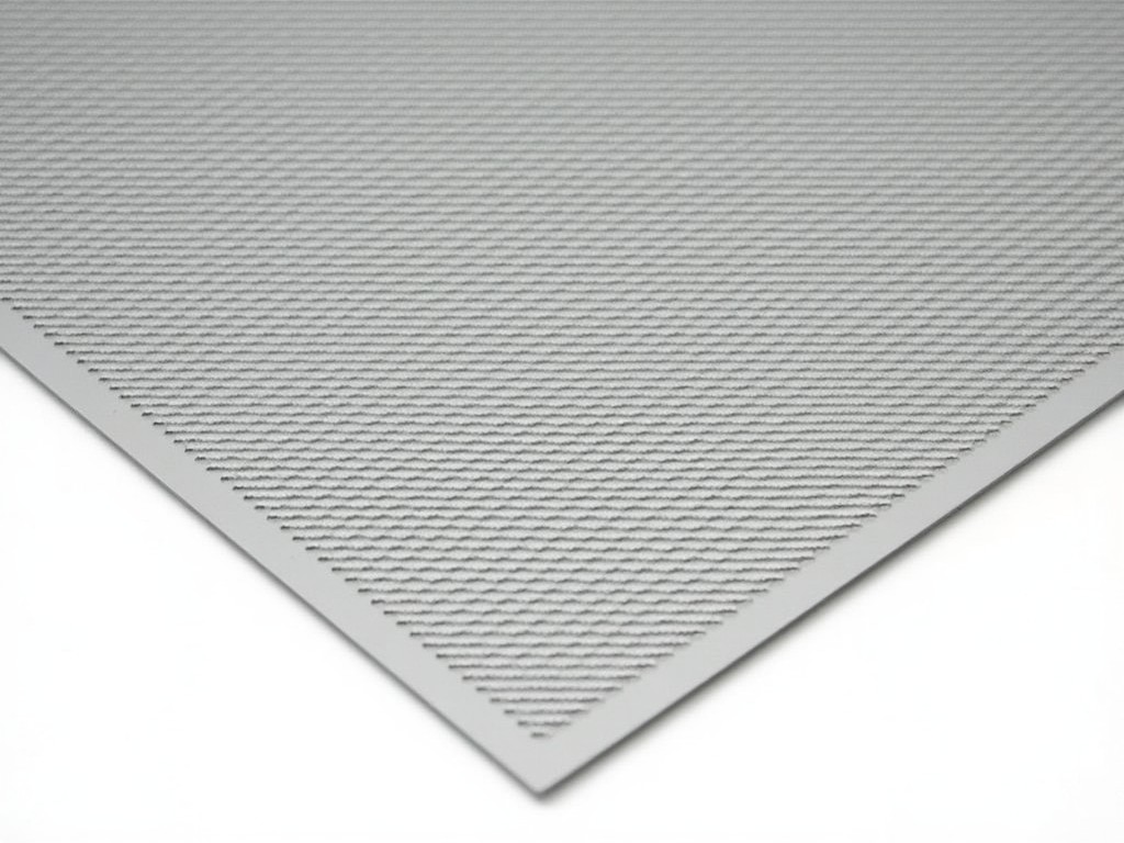
Perforated Metal Sheet for Ceiling
Perforated metal sheets used in ceiling applications combine functional performance with architectural flexibility. These panels are manufactured by punching precise hole patterns into metal substrates, enabling controlled acoustic absorption, airflow management, and light diffusion while maintaining structural integrity. The perforation geometry—hole size, shape, spacing, and open area percentage—directly influences the sheet’s behavior in environmental control systems.
Material Selection and Substrate Properties
Common substrates include cold-rolled steel, galvanized steel, aluminum, and stainless steel, each selected based on environmental exposure, load requirements, and finish compatibility. Steel substrates typically range from 0.5 mm to 1.5 mm in thickness, offering high strength-to-weight ratio suitable for suspended ceiling grids. Aluminum variants, while lighter, provide natural corrosion resistance and are often chosen for humid or coastal environments where weight reduction is critical.
Perforation Patterns and Open Area Design
Perforation patterns are engineered to meet specific acoustic or ventilation targets. Round, square, slotted, and hexagonal hole arrangements are standard, with open areas typically ranging from 10% to 60% depending on the application. For acoustic ceiling panels, patterns with 20–30% open area backed by absorbent material (such as mineral wool or fiberglass) achieve Noise Reduction Coefficients (NRC) between 0.60 and 0.85 in mid-frequency ranges, as validated per ASTM C423 testing protocols.
Surface Treatments and Finish Options
Post-perforation treatments enhance durability and aesthetics. Powder coating provides uniform color coverage and resistance to chipping, fading, and moisture ingress, with standard thicknesses between 60–80 μm. Anodizing is exclusive to aluminum substrates, forming a hard, translucent oxide layer that improves wear resistance while allowing metallic appearance. For industrial environments requiring chemical resistance, epoxy or polyurethane coatings may be applied, though these increase material cost and require precise curing controls.
Integration with Ceiling Systems
Perforated metal ceiling sheets are designed to interface with standard T-grid or concealed suspension systems. Edge treatments—such as hemmed, flanged, or rolled edges—ensure safe handling and secure engagement with grid components. Panel sizes commonly align with modular ceiling layouts (e.g., 600 mm × 600 mm or 600 mm × 1200 mm), though custom dimensions are feasible within manufacturing constraints of press brake and CNC punch capabilities. Weight per square meter varies with material and thickness; for example, 1.0 mm galvanized steel at 25% open area averages approximately 8.2 kg/m².
Thermal and Fire Performance Considerations
Metal substrates contribute minimally to thermal insulation but do not combust, making perforated sheets suitable for fire-rated ceiling assemblies when combined with approved backing materials. Aluminum melts at approximately 660°C, while steel retains structural integrity beyond 500°C depending on alloy and thickness. Fire performance classifications (e.g., ASTM E84 for surface burning characteristics) depend on the complete assembly—including substrate, perforation, backing, and finish—and must be evaluated per project-specific fire codes.
Customization and Manufacturing Constraints
Custom perforation layouts are achievable through CNC turret punching or laser cutting, allowing for variable hole density, gradient patterns, or branded geometries. However, minimum pitch (distance between hole centers) is constrained by material thickness and tooling strength—typically not less than 1.5× the material thickness to avoid tearing or excessive burr formation. Edge margins and hole-to-border distances must accommodate die clearance and prevent distortion during punching, usually requiring a minimum of 3–5 mm from the panel edge.
Quality Control and Inspection Criteria
Dimensional accuracy is verified via optical measurement or CMM, with tolerances typically held to ±0.5 mm for length and width, and ±0.1 mm for thickness. Perpendicularity and flatness are assessed using feeler gauges or laser scanners, with warpage limits generally under 2 mm per meter to ensure proper grid seating. Hole registration is inspected visually or via machine vision to confirm pattern consistency, particularly in architectural applications where visual alignment impacts perceived quality.
| Property | Typical Range or Value | Notes |
|---|---|---|
| Substrate Thickness | 0.5 mm – 1.5 mm | Depends on material and span requirements |
| Open Area Percentage | 10% – 60% | Selected based on acoustic/ventilation needs |
| Panel Weight (1.0 mm Galv. Steel) | ~8.2 kg/m² at 25% open area | Scales linearly with thickness and density |
| Minimum Hole Pitch | ≥1.5× material thickness | To prevent tooling damage and material failure |
| Edge Margin | ≥3–5 mm | Required for die clearance and flatness |
Applications in Commercial and Industrial Environments
In office and healthcare facilities, perforated metal ceilings contribute to speech privacy and noise reduction by absorbing mid-to-high frequency sound when paired with acoustic backer. In transportation hubs or industrial workshops, the same panels facilitate air return or exhaust when integrated with HVAC plenums, allowing pressure equalization without visual obstruction. Retail environments often utilize custom perforation patterns to diffuse lighting evenly while maintaining a modern aesthetic, reducing glare and hotspots from direct luminaires.
Ordering and Technical Support
To initiate a quotation, provide substrate material, thickness, desired perforation pattern (hole size, shape, pitch), open area target, panel dimensions, edge treatment, and finish specification. For acoustic performance targets, specify the required NRC or absorption coefficient and intended backing material. Lead times typically range from 2–4 weeks for standard configurations, with extended timelines for custom tooling or specialized coatings. Sample panels are available upon request to validate appearance, flatness, and hole consistency prior to full production.
For technical consultation or to request a quote, visit our contact page.
Request Technical Quote
More Products

Send Inquiry
If you are interested in our products, leave your information here and we will be in touch shortly.