Perforated Metal Sheet Sizes
Perforated metal sheets are engineered components defined by precise geometric relationships between hole pattern, open area, sheet thickness, and overall dimensions. Understanding these
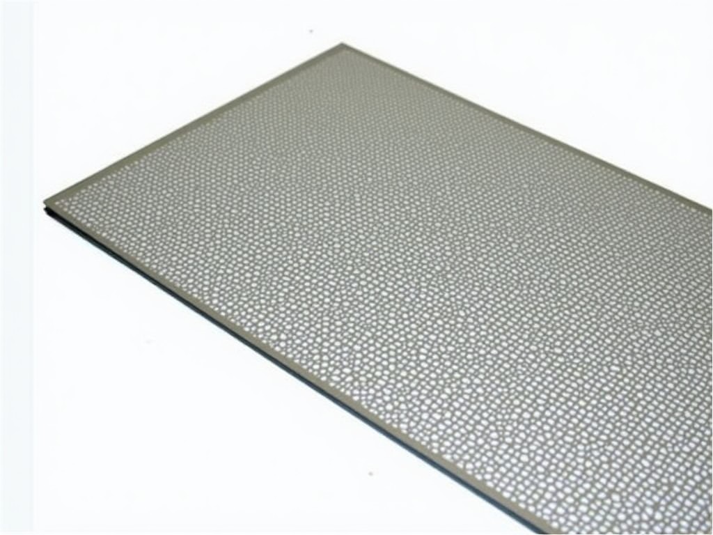
Perforated Metal Sheet Sizes: Technical Specifications and Standard Dimensions
Perforated metal sheets are engineered components defined by precise geometric relationships between hole pattern, open area, sheet thickness, and overall dimensions. Understanding these interdependent variables is essential for structural design, filtration efficiency, acoustic performance, and manufacturing feasibility. This page details standard size ranges, material constraints, and dimensional tolerances to support accurate specification and procurement.
Standard Sheet Dimensions and Tolerances
Industrial perforated sheets are typically supplied in rectangular formats with length and width dimensions governed by material handling capabilities, press bed sizes, and transportation logistics. Common stock sizes range from 1000 mm × 2000 mm to 1500 mm × 3000 mm, with custom lengths achievable through coil processing or longitudinal cutting. Width is often limited by the maximum die width of perforation presses, typically not exceeding 1800 mm for standard tooling without intermediate splicing.
Dimensional tolerances for overall sheet size follow industry standards such as ASTM A1011/A1018 for steel or EN 10143 for stainless steel, generally permitting ±3 mm deviation in length and width for sheets under 3000 mm. Squareness tolerances are typically controlled to within 2 mm per meter of edge length. These tolerances ensure compatibility with framing systems, welding fixtures, and downstream fabrication processes while accounting for material springback and thermal expansion during perforation.
Thickness Range and Material Constraints
Sheet thickness directly influences the feasibility of specific hole patterns and the structural integrity of the perforated section. Thinner materials (0.5 mm–1.5 mm) allow for smaller hole diameters and higher open areas but are prone to deformation during perforation without adequate support. Thicker sections (2.0 mm–6.0 mm) require higher press forces and may limit the minimum pitch-to-diameter ratio, increasing the risk of tool wear or material fracture.
Maximum achievable thickness depends on material tensile strength and perforation geometry. For example, low-carbon steel can typically be perforated up to 6.0 mm with round holes ≥3× material thickness, while stainless steel grades like 304 or 316 are often limited to 4.0 mm for equivalent patterns due to higher work hardening rates. Aluminum alloys permit thicker sections (up to 8.0 mm) for the same hole size owing to lower yield strength, though edge burr formation may require secondary deburring.
Hole Pattern Parameters and Open Area Calculations
The functional performance of perforated sheet is determined by hole shape, size, pitch (center-to-center distance), and arrangement (staggered or straight line). Open area percentage—the ratio of hole surface to total sheet surface—is calculated from these parameters and directly affects airflow, light transmission, sound absorption, and liquid filtration capacity. Standard round hole patterns range from 1.0 mm to 50.0 mm diameter, with pitches typically 1.5× to 3× the hole diameter to maintain ligament strength.
Staggered 60° patterns are most common due to optimal material utilization and uniform strength distribution. For instance, a 5.0 mm diameter hole on a 8.0 mm pitch in a staggered layout yields approximately 30% open area. Square and slotted holes offer directional flow characteristics but reduce open area for equivalent hole dimensions due to corners or end radii. Minimum ligament width (material between holes) should generally not fall below 1.0 mm to prevent tearing during forming or handling.
Material-Specific Size Limitations
Different metals exhibit distinct behaviors during perforation that impose practical limits on sheet size and thickness combinations. Hot-rolled steel sheets are susceptible to scale-induced tool wear and may require pickling before perforation to maintain hole quality, particularly for thicknesses over 3.0 mm. Cold-rolled stock offers better surface finish and tighter thickness tolerances but is more prone to edge cracking when perforated near the material limits.
Stainless steel grades require lubrication and frequent tool polishing to prevent galling, especially in thicknesses exceeding 2.5 mm. This often necessitates slower press speeds, affecting production efficiency for large sheets. Aluminum and its alloys, while easier to perforate, exhibit greater springback and are more sensitive to dimensional changes caused by residual stress relief, requiring stress-relief annealing for critical flatness applications in widths over 1200 mm.
Typical Size Ranges by Application
Application-driven requirements often dictate preferred size envelopes. Architectural facade panels frequently utilize sheets up to 1200 mm × 3000 mm to minimize joint lines and accommodate standard framing modules. Industrial screens and guards are commonly supplied in 1000 mm × 2000 mm blanks for ease of handling and welding into frames. Filtration elements in hydraulic or pneumatic systems may use smaller formats (500 mm × 500 mm) to fit within cartridge housings, while acoustic panels benefit from larger continuous widths to reduce seams in ceiling or wall installations.
Conveyor perforations for food processing or drying applications often require widths matching belt standards (e.g., 600 mm, 900 mm, 1200 mm) with lengths determined by conveyor trajectory. In each case, the selected size must balance material yield, press capacity, flatness retention, and downstream processing constraints such as bending, framing, or coating compatibility.
| Application | Typical Width Range | Typical Length Range | Common Thickness Range |
|---|---|---|---|
| Architectural Facade | 900–1200 mm | 2400–3600 mm | 0.8–2.0 mm |
| Industrial Machine Guard | 1000–1500 mm | 1000–2000 mm | 1.5–3.0 mm |
| HVAC Filtration | 300–600 mm | 300–1000 mm | 0.5–1.2 mm |
| Acoustic Panel | 600–1200 mm | 1200–2400 mm | 0.6–1.5 mm |
| Conveyor Perforation | 600–1200 mm | As required | 1.0–2.5 mm |
Custom Size Considerations and Processing Limits
While standard sizes offer logistical advantages, many projects require non-standard dimensions to match specific equipment envelopes or architectural modules. Maximum coil width for continuous perforation lines typically ranges from 1500 mm to 1800 mm, enabling production of custom lengths through slitting and cut-to-length operations. However, widths beyond 1800 mm often necessitate transverse splicing or multiple press passes, introducing potential alignment variations and increased handling complexity.
Length limitations are primarily governed by material handling equipment, coil weight, and flatness control. Sheets exceeding 4000 mm may require intermediate tension leveling to prevent wave formation, particularly in thinner gauges. For thicknesses over 4.0 mm, maximum practical length is often reduced to 3000 mm due to press stroke limitations and material handling safety considerations. Custom sizes should be evaluated for press brake compatibility, as excessive length can induce bowing during bending operations.
Tolerancing for Secondary Operations
When perforated sheets undergo subsequent fabrication such as bending, welding, or framing, initial dimensional tolerances must accommodate expected deformation. Bend allowance calculations require knowledge of material thickness, grain direction, and inner bend radius—factors influenced by the perforation pattern. Areas with high open area may exhibit reduced bending stiffness, necessitating wider bend radii or additional support to prevent cracking along ligament lines.
Welding-induced distortion is more pronounced in thin, high-open-area sheets due to uneven heat dissipation. Pre-cutting to slightly oversized dimensions and allowing for post-weld straightening is common practice. For assemblies requiring tight tolerances, such as precision screens or optical baffles, stress-relief annealing after perforation and leveling prior to final machining can improve dimensional stability. These considerations should be integrated into the initial size specification to avoid rework or scrap.
More Products

Send Inquiry
If you are interested in our products, leave your information here and we will be in touch shortly.