Perforated Metal Soffit Panels
Perforated metal soffit panels are engineered architectural components designed to cover the underside of building overhangs, eaves, and canopy structures while providing controlled airflow, acoustic
Perforated Metal Soffit Panels
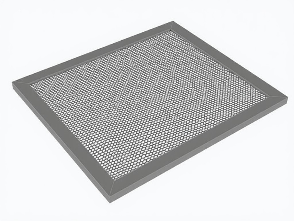
Perforated metal soffit panels are engineered architectural components designed to cover the underside of building overhangs, eaves, and canopy structures while providing controlled airflow, acoustic performance, and visual continuity. These panels consist of precision-formed metal sheets with strategically distributed openings that balance functional requirements with aesthetic intent. Unlike solid soffit materials, perforated variants enable passive ventilation without compromising weather protection or creating visual clutter from exposed mechanical systems.
Material Selection and Performance Characteristics
Material choice directly influences panel longevity, corrosion resistance, weight, and fabrication tolerances. Aluminum alloys (3003-H14, 5052-H32) are commonly selected for exterior applications due to their natural oxide layer formation, which provides inherent protection against atmospheric corrosion without additional coatings. For harsh environments involving salt spray or industrial pollutants, marine-grade aluminum or stainless steel grades 304 and 316 offer enhanced resistance through higher chromium and nickel content. Galvanized steel (G90 coating) presents a cost-effective alternative where weight is less critical, though it requires periodic inspection in high-moisture zones to prevent edge corrosion propagation.
Panel thickness typically ranges from 0.032" to 0.063" for aluminum and 0.024" to 0.048" for steel, selected based on span requirements, wind load calculations, and deflection limits. Thinner gauges reduce material cost and dead load but increase susceptibility to oil-canning under thermal cycling; thicker gauges improve rigidity and impact resistance at the expense of increased weight and fabrication force requirements. All materials undergo mill certification verification to ensure chemical composition and mechanical properties align with ASTM B209 (aluminum) or ASTM A653/A1008 (steel) standards prior to perforation.
Perforation Patterns and Open Area Engineering
The perforation pattern governs both functional performance and visual appearance. Open area percentage—calculated as the ratio of hole surface area to total panel area—directly affects airflow capacity, sound transmission, and light diffusion. Common patterns include staggered 60-degree hole arrangements (maximizing open area for given hole size), straight rows (simplifying alignment during installation), and custom geometric layouts (architectural accents). Hole diameters typically range from 1/16" to 1/4", with spacing between hole centers determining open area: a 1/8" hole on 1/4" centers yields approximately 25% open area, while the same hole size on 3/8" centers reduces open area to about 11%.
Engineers select perforation density based on dual criteria: minimum required ventilation rate (cfm per square foot) derived from ASHRAE standards for attic or soffit ventilation, and maximum allowable sound transmission loss for acoustic control. Higher open areas improve airflow but reduce structural rigidity and increase visibility of underlying framing; lower open areas enhance privacy and acoustic barrier performance but may necessitate larger soffit volumes to achieve equivalent air exchange. Custom perforation layouts allow architects to integrate branding elements, wayfinding cues, or diffuse lighting effects while maintaining performance specifications.
Fabrication Processes and Dimensional Stability
Panel flatness and edge integrity are critical for seamless installation and long-term appearance. Perforation is typically executed via CNC turret punches or laser systems after coil leveling to eliminate residual stresses from milling. Punched holes may exhibit slight burrs on the exit side, which are removed through vibratory deburring or brushing to prevent handling injuries and ensure consistent coating adhesion. Laser perforation produces cleaner edges with minimal thermal distortion but requires precise power and speed calibration to avoid micro-cracking in heat-sensitive alloys.
Following perforation, panels undergo roll forming or brake bending to create peripheral flanges, stiffeners, or interlocking edges that facilitate attachment to substrate framing. Flange heights generally range from 3/4" to 1-1/2", providing sufficient fastening surface while minimizing visible reveal. Bend radii are maintained above material-specific minimums (typically 1x thickness for aluminum, 2x for steel) to prevent cracking during forming. All formed edges receive uniform coating coverage to prevent localized corrosion initiation points.
Surface Treatments and Finish Durability
Finish systems protect the substrate while contributing to aesthetic consistency and solar reflectance. Anodized aluminum (Class I, 0.7 mil minimum thickness) provides translucent, metallic appearance with UV stability and hardness exceeding 250 Vickers. For opaque finishes, fluoropolymer-based coatings (70% PVDF) offer 20+ year color retention and chalk resistance per ASTM D2244 and D4214, with typical dry film thickness of 1.2 mils primer + 0.8 mils topcoat. Powder coatings (epoxy primers + polyurethane topcoats) provide cost-effective alternatives for interior or semi-exposed locations, though they exhibit lower UV resistance than fluoropolymers in direct sunlight.
Finish selection considers project location, maintenance accessibility, and lifecycle cost analysis. Coastal installations benefit from anodized or 70% PVDF finishes due to chloride resistance, while inland applications may utilize standard polyester powders with acceptable 10-year performance. All finishes undergo adhesion testing (ASTM D3359) and salt spray exposure (ASTM B117) validation prior to project approval. Touch-up procedures are defined for field repairs, ensuring color consistency over the product lifespan.
Structural Design and Installation Considerations
Soffit panels function as non-structural cladding but must resist wind uplift, differential deflection, and seismic movement without permanent deformation or fastener failure. Design wind pressure is calculated per ASCE 7-16 using components and cladding zones for soffit applications, typically yielding suction pressures of 20-40 psf depending on building height, exposure category, and importance factor. Panel systems transfer these loads to the building structure through mechanical fasteners (typically #8-10 stainless steel screws) spaced at 6-8" intervals along supported edges, with spacing reduced in high-wind zones or for larger panel formats.
Thermal movement accommodation is essential to prevent buckling or fastener overload. Aluminum expands approximately 12.8 µin/in°F; a 12-foot panel experiences ~0.23" length change over a 100°F temperature swing. Installation details incorporate slotted holes, floating clips, or perimeter expansion gaps (typically 1/8" per 10 feet of panel length) to allow movement without inducing stress. Deflection limits are generally set to L/180 for soffit applications to prevent visible sagging under uniform load, verified through finite element analysis during system design.
Typical Applications Across Building Types
Perforated metal soffit panels serve distinct functions depending on the building’s operational requirements and environmental context. In commercial office towers, they provide continuous ventilation for plenum spaces while maintaining a clean, monolithic appearance that complements curtain wall systems. The controlled airflow prevents moisture accumulation and reduces HVAC load by facilitating passive heat extraction from ceiling cavities. In parking structures, perforated soffits enable natural air exchange to dissipate vehicle exhaust and gasoline vapors, meeting mechanical code requirements for open parking facilities without relying on powered ventilation systems.
Educational institutions utilize these panels in auditoriums and gymnasiums where acoustic performance is critical; the perforations allow sound transmission to absorptive backing materials (such as mineral wool or fabric-wrapped fiberglass) located in the plenum, reducing reverberation time without compromising ceiling aesthetics. Healthcare facilities specify perforated soffits in corridors and waiting areas to support infection control strategies—enabling air changes that dilute airborne contaminants while maintaining smooth, cleanable surfaces that resist microbial growth. Industrial facilities apply them in machine rooms and substations where equipment heat dissipation requires unobstructed convection paths, with perforation patterns sized to match thermal exhaust volumes.
Quality Assurance and Dimensional Control
Dimensional accuracy ensures consistent fit during installation and prevents visual misalignment across large facade areas. Panel length and width tolerances are typically held to ±1/16" for cut-to-size pieces, with squareness deviation limited to 1/8" over 4 feet to maintain consistent reveal patterns. Perforation registration is controlled to ±0.010" hole-to-hole position variation, ensuring pattern consistency across multiple panels. Flatness is verified using optical comparators or laser scanning, with deviation from a reference plane not exceeding 0.030" over any 24-inch span to prevent shadowing or oil-canning effects under oblique lighting.
Material thickness is validated using micrometers at multiple points per panel, with average thickness maintained within ±0.002" of nominal. Coating thickness is measured via magnetic or eddy current probes per ASTM D7091, with spot checks conducted on every batch. Adhesion testing (cross-hatch tape test) is performed on 100% of lots, with any failure triggering full lot inspection. Packaging employs protective interleaving between panels and edge guards to prevent abrasion during transit, with units unitized on pallets and stretch-wrapped for moisture resistance.
Comparison of Common Material Options
| Property | Aluminum 3003-H14 | Aluminum 5052-H32 | Stainless Steel 304 | Galvanized Steel (G90) |
|---|---|---|---|---|
| Density (lb/in³) | 0.098 | 0.097 | 0.289 | 0.284 |
| Tensile Strength (ksi) | 16-19 | 33-38 | 75-85 | 45-55 |
| Yield Strength (ksi) | 6-9 | 21-26 | 30-35 | 25-35 |
| Thermal Expansion (µin/in°F) | 12.8 | 12.6 | 9.6 | 6.7 |
| Typical Use Case | Standard exterior soffits | High-wind or impact zones | Coastal or industrial corrosion | Budget-constrained interiors |
Material selection balances mechanical demands, environmental exposure, and lifecycle cost. Aluminum 3003-H14 offers adequate strength for most soffit applications with minimal weight penalty, making it suitable for large-span installations where dead load affects structural design. 5052-H32 provides approximately double the yield strength of 3003, beneficial in regions with high wind loads or where panel deflection limits are stringent. Stainless steel 304 delivers superior corrosion resistance in chloride-rich environments but increases dead load by nearly 3x compared to aluminum, requiring stronger support structures. Galvanized steel provides an economical option for interior soffits or temporary installations, though its zinc coating may degrade over time in humid or polluted atmospheres, necessitating periodic maintenance or repainting.
Customization Logic and Project-Specific Adaptation
Customization follows a systematic approach to align panel performance with project specifications without compromising manufacturability. The process begins with defining functional requirements: required ventilation rate (cfm/ft²), acoustic transmission loss (if applicable), maximum allowable deflection, and finish durability expectations. These parameters drive perforation pattern selection—open area is calculated to meet ventilation needs, then hole size and spacing are adjusted to satisfy acoustic targets or architectural visibility constraints. Structural analysis confirms that the selected gauge and flange design can withstand prescribed wind and seismic loads with appropriate fastener spacing.
Finish selection is derived from environmental exposure classification (per ISO 12944) and maintenance access limitations. For example, a parking garage in a coastal zone might specify 5052-H32 aluminum with 70% PVDF coating in a custom bronze shade to match adjacent metal panels, with 3/16" holes on 5/16" centers (28% open area) to balance exhaust ventilation with glare control from vehicle headlights. Dimensional customization includes panel widths (typically 12-24" for handling efficiency), lengths (up to 20' for coil-fed processing), and edge profiles (hemmed, flanged, or hooked for specific attachment systems). All customizations are documented in shop drawings that include perforation layout diagrams, cross-sectional details, and installation sequences.
Environmental and Lifecycle Attributes
Perforated metal soffit panels contribute to sustainable building strategies through material efficiency, recyclability, and operational energy savings. Aluminum and steel panels contain high recycled content (typically 30-85% post-consumer) and are 100% recyclable at end-of-life, supporting circular economy principles. The lightweight nature of aluminum reduces transportation energy compared to heavier cladding options. During building operation, ventilated soffits reduce attic temperatures by 10-20°F in cooling climates, decreasing cooling load and extending roof membrane life by minimizing thermal cycling stress.
Finish systems are evaluated for volatile organic compound (VOC) content, with water-based and powder coatings offering lower emissions than solvent-borne alternatives. Reflective finishes (typically >0.6 solar reflectance) reduce heat island effect by lowering surface temperatures compared to dark absorptive coatings. Water runoff from finished panels is inert and non-toxic, meeting stormwater quality requirements in most jurisdictions. Manufacturers provide environmental product declarations (EPDs) upon request, detailing global warming potential, ozone depletion, and other lifecycle impact categories per ISO 14025.
Ordering Information and Technical Support
To initiate a quotation, project teams should provide architectural drawings showing soffit locations, dimensions, and attachment conditions; specified performance requirements including ventilation rate, acoustic criteria, and finish durability; and environmental exposure details (e.g., proximity to coast, industrial pollutants). For custom perforation patterns, a scaled sketch or CAD file indicating hole size, spacing, and layout intent is required. Material samples with proposed finishes are available for approval prior to production, allowing verification of color, gloss, and texture under project-specific lighting conditions.
Lead times typically range from 3-6 weeks for standard configurations, extending to 8-12 weeks for highly customized patterns or special finishes. Shipping is facilitated via LTL or dedicated truckload with protective packaging designed to prevent edge damage and surface abrasion. Technical support includes assistance with perforation pattern optimization, wind load calculations, and detailing for complex geometries such as curved soffits or penetrations for lighting fixtures. All product information, including test reports and installation guides, is accessible through the manufacturer’s technical portal.
More Products

Send Inquiry
If you are interested in our products, leave your information here and we will be in touch shortly.