Oem Temporary Pool Fence No Drilling
Temporary pool fencing systems designed for rapid deployment without permanent modifications to hardscape or substrate provide critical safety barriers during construction, renovation, or seasonal
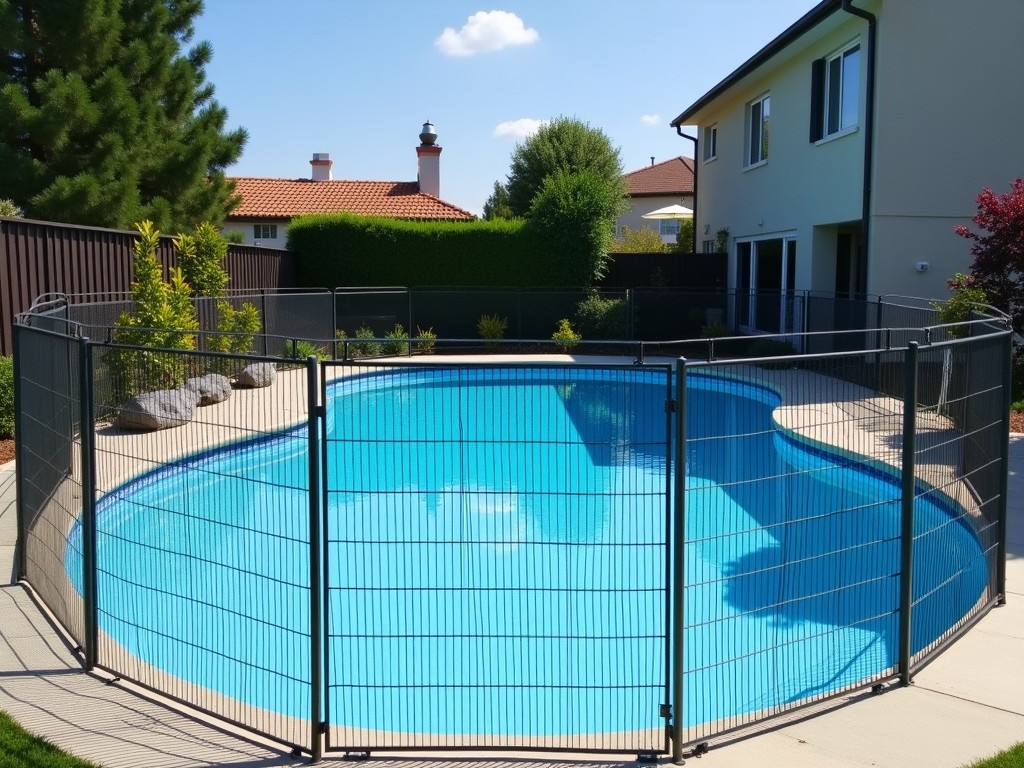
OEM Temporary Pool Fence No Drilling
Temporary pool fencing systems designed for rapid deployment without permanent modifications to hardscape or substrate provide critical safety barriers during construction, renovation, or seasonal use. These systems eliminate the need for core drilling, anchoring, or adhesive bonding to concrete, pavers, or decking, preserving surface integrity while meeting temporary barrier requirements. Engineers and facility managers specify no-drill solutions to reduce installation time, avoid substrate damage, and simplify removal at project completion. The following details outline the structural, material, and installation characteristics of OEM-specified temporary pool fences that operate without drilling.
Structural Design and Load Path
The fence system relies on weighted bases and friction-resistant interfaces to transfer lateral loads from impact or wind into the ground through gravity, rather than mechanical fixation. Each panel connects to a base unit via a pinned or clamped joint that allows angular adjustment for contour following while maintaining lateral rigidity. Base units typically incorporate recessed cavities for sand, water, or dense ballast (such as steel shot or recycled aggregate) to achieve sufficient mass to resist overturning moments calculated per local safety codes for pool barriers. The absence of ground penetration means load distribution depends entirely on base footprint size and material density, requiring careful engineering of the base-panel interface to prevent sliding or tipping under dynamic loads.
Panel height is standardized at 48 inches (1220 mm) to comply with most residential pool barrier regulations, with vertical pickets spaced no more than 4 inches apart to prevent sphere passage. Horizontal rails are typically elliptical or rectangular tubing to maximize bending resistance while minimizing visual obstruction. The fence panel itself acts as a shear-resisting truss, where the top and bottom rails resist bending and the vertical infill transfers load between them. Deflection under specified load (usually 50 lbs applied at mid-span) is limited to less than 1 inch to maintain barrier integrity and prevent climbability.
Ballast Base Engineering
Base units are commonly molded from high-density polyethylene (HDPE) or linear low-density polyethylene (LLDPE) due to their impact resistance, UV stability, and ability to be molded into complex geometries with integrated reinforcement ribs. Wall thickness typically ranges from 0.15 to 0.25 inches (3.8 to 6.4 mm) to balance stiffness with weight, while the base footprint averages 24 inches square (610 mm) to provide adequate resistance to sliding. Internal baffles within the base prevent ballast shifting during movement, ensuring consistent center of gravity. Drain plugs or sealed fill ports allow for water or sand filling and emptying without leakage.
For applications requiring higher mass in a compact footprint, some OEM designs incorporate a steel-reinforced frame within the HDPE shell, allowing the use of denser ballast like steel shot or crushed granite. The interface between base and panel often features a stainless steel pin or reinforced nylon bushing to resist wear from repeated assembly and disassembly. Surface textures on the base bottom may include rubber pads or molded treads to increase friction coefficient on smooth surfaces like polished concrete or tile, reducing reliance on mass alone for slip resistance.
Material Selection and Environmental Resistance
Fence panels are predominantly constructed from powder-coated aluminum or galvanized steel to balance strength, weight, and corrosion resistance in wet, chlorinated, or salt-exposed environments. Aluminum alloys such as 6063-T5 are commonly extruded for rails and pickets, offering tensile strength around 25,000 psi with excellent resistance to pitting and crevice corrosion when coated. Steel components, when used, are typically hot-dip galvanized to a minimum Z275 coating weight (0.9 oz/ft² per side) or painted with epoxy primer and polyurethane topcoat for enhanced durability in aggressive chemical exposures.
UV stabilizers are integrated into the polyethylene base formulation to prevent embrittlement and cracking under prolonged sun exposure, with typical additives including hindered amine light stabilizers (HALS) and carbon black. Colorants are dispersed throughout the base material during molding to avoid surface wear revealing uncolored substrate. All metal-to-plastic interfaces are designed to avoid galvanic corrosion by using insulating nylon washers or maintaining material compatibility (e.g., aluminum to HDPE). Joints and fasteners are typically stainless steel (Grade 304 or 316) to prevent staining and maintain appearance over multiple use cycles.
Installation and Reconfiguration Logic
Installation begins with positioning base units along the desired barrier perimeter, typically spaced at 6 to 8 feet (1.8 to 2.4 m) on center depending on panel length and expected load. Ballast is added to each base—water being the most common due to ease of filling and emptying, with approximately 50 lbs (23 kg) per base providing sufficient resistance for standard wind and impact conditions. Panels are then lifted into place and connected to the base via a drop-in pin or swing-clamp mechanism that engages a receiver molded into the base top surface. The connection allows for ±15 degrees of angular adjustment to accommodate curves or uneven terrain without inducing stress on the panel.
No tools are required for assembly or disassembly, enabling rapid deployment by facility staff or contractors. Reconfiguration involves lifting the panel free, moving the base, and reinserting the panel—processes that take seconds per unit. The absence of drilling, adhesives, or permanent fasteners means the underlying surface remains unaltered, making the system ideal for rented properties, historic sites, or surfaces with waterproofing membranes that cannot be penetrated. Storage between uses involves draining bases, stacking panels flat or vertically, and storing components in a dry, shaded area to prolong material life.
Customization Parameters for OEM Integration
OEM customers specify variations in panel length, height, infill pattern, and base geometry to match brand aesthetics, site constraints, or regional safety codes. Common panel lengths range from 4 to 8 feet (1.2 to 2.4 m), with longer spans requiring intermediate stiffeners or deeper base sections to control deflection. Height adjustments above 48 inches are possible but require recalculation of ballast requirements due to increased overturning moment. Infill options include vertical pickets, mesh panels, or perforated metal sheets, each affecting wind load and visibility differently.
Base color, texture, and branding areas are customizable during molding, allowing for logo integration or color coding for different zones (e.g., red for restricted access, yellow for caution). Connection hardware can be adapted to proprietary locking mechanisms for tamper resistance or simplified for tool-free use by non-technical personnel. Packaging options include bulk palletizing of bases and panels or kit packaging for specific project quantities, with labeling designed for easy identification of components during field assembly.
Quality Control and Validation Approach
Manufacturing quality control focuses on dimensional consistency of molded bases, tensile strength of coated metal components, and functionality of connection mechanisms under repeated cycling. Base molding is inspected for wall thickness uniformity using ultrasonic gauging, with typical tolerance of ±0.02 inches (0.5 mm) on critical sections. Panel components undergo bend and torsion testing to verify stiffness, while connection points are cycle-tested for 500+ insertions to ensure wear resistance. Final assembly verification includes a functional test where the assembled barrier is subjected to a lateral load equivalent to 50 lbs at mid-span, with deflection measured and recorded.
Material certifications are maintained for resin grades (e.g., FDA-compliant HDPE for potable water contact, if applicable) and metal coatings (e.g., AAMA 2603 or 2605 for powder coating). UV resistance is validated through accelerated weathering testing (ASTM G154) equivalent to 1,000 hours of sun exposure. While specific test values are project-dependent, the OEM follows documented procedures for incoming material verification, in-process checks, and final product validation. Traceability is maintained via lot numbers on bases and panels, linking raw material batches to finished goods.
Packaging is designed to prevent deformation during transit, with bases nested or stacked and panels protected by edge guards or corrugated dividers. Unit loads are secured to pallets with stretch wrap or straps, and shock indicators may be included for sensitive shipments. Instructions for assembly, ballasting, and inspection are provided in multiple languages as required, with clear diagrams showing proper base filling levels and panel engagement. The OEM maintains a technical file for each product variant, accessible to customers upon request for audits or regulatory submissions.
| Parameter | Typical Value or Range | Notes |
|---|---|---|
| Panel Height | 48 in (1220 mm) | Standard for pool barrier compliance; customizable upon request |
| Panel Length | 4–8 ft (1.2–2.4 m) | Longer spans may require intermediate reinforcement |
| Base Footprint | 24 in × 24 in (610 × 610 mm) | Optimized for stability and handling |
| Ballast Capacity (Water) | ~50 lbs (23 kg) per base | Adjustable; sand or shot increases mass |
| Material – Panel | Powder-coated aluminum (6063-T5) or galvanized steel | Selected based on environment and weight requirements |
| Material – Base | HDPE/LLDPE with UV stabilizers | Wall thickness: 0.15–0.25 in (3.8–6.4 mm) |
| Connection Type | Pin-and-receiver or swing-clamp | Tool-free; allows angular adjustment |
| Max Deflection @ 50 lb Load | <1 in (25 mm) | Measured at mid-span of panel |
The no-drill temporary pool fence serves as a practical solution where safety barriers are required temporarily and substrate preservation is critical. By relying on engineered ballast and friction-based stability rather than ground penetration, the system avoids compromising waterproofing, structural integrity, or aesthetic finishes. OEMs benefit from the ability to tailor dimensions, materials, and branding to specific project needs while maintaining a consistent installation methodology that reduces labor training requirements and field errors. The focus on reusable, tool-free assembly supports sustainability goals by minimizing waste and enabling multiple deployment cycles across different sites or seasons.
For technical specifications, customization requests, or sample evaluation, contact the OEM directly to discuss project-specific requirements including load conditions, surface types, regulatory jurisdiction, and expected cycle life. Detailed CAD models, material data sheets, and installation guides are available upon request to support integration into project planning and safety documentation.
Product Categories

Send Inquiry
If you are interested in our products, leave your information here and we will be in touch shortly.