China 4X4 Welded Wire Mesh For Concrete
Welded wire mesh with a 4-inch by 4-inch grid pattern is a standardized reinforcement solution widely used in concrete construction to control cracking and improve structural performance.
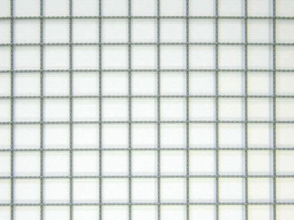
China 4x4 Welded Wire Mesh for Concrete Reinforcement
Welded wire mesh with a 4-inch by 4-inch grid pattern is a standardized reinforcement solution widely used in concrete construction to control cracking and improve structural performance. Manufactured from cold-drawn steel wire welded at each intersection, this product provides uniform tensile strength distribution across the slab or wall. The 4x4 spacing offers a balance between material efficiency and reinforcement effectiveness for typical residential, commercial, and light industrial applications.
The mesh is produced to meet common international specifications, with wire diameters typically ranging from BWG 8 to BWG 16 (4.06mm to 1.63mm) depending on load requirements. Sheets are commonly supplied in standard sizes such as 2m x 3m or 2.4m x 6m, though custom dimensions are available to minimize cutting waste on-site. Edge overhangs are maintained to ensure proper lap splicing when multiple sheets are installed.
Welding is performed using automated resistance welding equipment, creating strong, consistent joints that maintain the integrity of the grid under deformation. The weld strength typically exceeds 90% of the parent wire’s tensile strength, ensuring the mesh behaves as a unified reinforcement system. After welding, the mesh may be left bare (black) or treated with a protective coating depending on environmental exposure.
Material Composition and Mechanical Properties
The base material is low-carbon steel wire, selected for its weldability, ductility, and consistent mechanical behavior after cold drawing. Typical tensile strength ranges from 450 MPa to 650 MPa, with yield strength between 350 MPa and 500 MPa, depending on the wire gauge and drawing process. Elongation at break generally falls between 10% and 20%, allowing the mesh to deform plastically before failure, which helps absorb energy during cracking.
Chemical composition is controlled to ensure reliable welding performance, with carbon content usually kept below 0.12% to minimize brittleness in the heat-affected zone. Manganese and silicon levels are adjusted to support deoxidation and strength without compromising ductility. Sulfur and phosphorus are kept low (<0.045%) to avoid hot shortness during welding.
For environments with moderate corrosion risk, such as indoor slabs or exterior walls with adequate concrete cover, galvanized coatings (zinc or zinc-aluminum) are available. Coating thickness typically ranges from 20 to 50 microns, providing sacrificial protection that extends service life in humid or mildly alkaline conditions. Fusion-bonded epoxy or PVC coatings are options for higher corrosion resistance, though they add cost and require careful handling to avoid damage during installation.
Standard Specifications and Dimensional Tolerances
| Parameter | Typical Range | Notes |
|---|---|---|
| Wire Diameter (BWG) | 8 to 16 | 4.06mm to 1.63mm |
| Grid Spacing | 101.6mm x 101.6mm (4"x4") | Nominal; actual ±2.5mm |
| Sheet Width | 0.6m to 2.4m | Custom widths available |
| Sheet Length | 1.2m to 6.0m | Standard lengths: 2m, 2.4m, 3m, 6m |
| Wire Tensile Strength | 450–650 MPa | Depends on wire grade and drawing |
| Weld Shear Strength | ≥90% of wire tensile | Tested per ASTM A1064 |
| Flatness Tolerance | ≤5mm deviation over 2m | Measured on flat surface |
Dimensional tolerances are controlled during production to ensure ease of placement and consistent concrete cover. Wire diameter follows BWG standards with ±0.08mm tolerance, while longitudinal and transverse wire spacing is held to ±2.5mm to maintain grid alignment. Sheet squareness is verified at the corners, with diagonal difference typically kept under 5mm per meter of width to prevent twisting during handling.
Flatness is critical for proper concrete encapsulation; excessive curl can lead to uneven cover and potential corrosion initiation. The mesh is tension-leveled during manufacturing to limit residual stress, with flatness verified before bundling. Edge wires are often slightly heavier (e.g., BWG 6 or 8) to resist damage during bundling, transport, and on-site handling, ensuring the mesh retains its shape until placement.
Applications in Concrete Construction
In slab-on-ground applications, 4x4 welded wire mesh is placed at mid-depth or in the upper third of the slab thickness to control shrinkage and temperature cracking. The uniform grid distributes tensile stresses across a wide area, preventing localized cracking that could lead to spalling or water ingress. For typical 100mm to 150mm thick residential or light commercial slabs, BWG 10 or BWG 12 wire provides adequate crack control under normal loading.
In wall construction, particularly for precast panels or tilt-up systems, the mesh serves as primary crack control reinforcement. Vertical and horizontal wires resist cracking due to drying shrinkage, thermal expansion, and handling stresses. When used in insulated concrete forms (ICFs), the mesh is embedded in the concrete layer to improve impact resistance and reduce cracking at corners and openings.
For pavement overlays and repair work, the mesh helps bridge existing cracks and prevents reflective cracking in the new layer. It is also used in precast elements such as stair landings, lintels, and architectural panels where handling stresses during demolding and transport require distributed reinforcement. In all cases, proper concrete cover (minimum 20mm for dry interior, 30–40mm for exterior) is essential to protect the steel from corrosion and ensure bond development.
Customization Options and Ordering Considerations
Wire diameter, sheet dimensions, and coating type can be adjusted to match specific project requirements. For higher load applications such as industrial floors or heavy-duty pavements, thicker wires (BWG 6 or 8) may be specified to increase tensile capacity. Conversely, for non-structural crack control in thin toppings or plaster bases, lighter wires (BWG 14 to 16) reduce material cost while still providing adequate reinforcement.
Sheet size optimization reduces labor and waste; for example, supplying mesh in widths that match standard formwork dimensions (e.g., 1.2m for residential forms) minimizes cutting. Custom lengths allow for single-piece placement in long walls or slabs, eliminating laps that can create weak points. Edge treatments such as bent-up wires or lugs are available to improve anchorage in beams or column stubs.
Coating selection depends on exposure conditions: bare steel for dry, enclosed environments; galvanized for general exterior use; epoxy-coated for chloride-exposed areas like parking garages or coastal structures. When ordering, providing the concrete cover requirement, expected crack width limits, and exposure class helps the supplier recommend the appropriate wire gauge and coating. Lead times typically range from 2 to 4 weeks for standard specifications, with longer timelines for custom coatings or non-standard dimensions.
Quality Control and Testing Procedures
Quality assurance begins with incoming wire inspection, where diameter, tensile strength, elongation, and coating adhesion (if applicable) are verified against mill certificates. Each batch is tested for mechanical properties before welding to ensure consistency. During production, weld strength is monitored through regular destructive testing of samples, with shear and tension tests performed per ASTM A1064 or equivalent standards.
Dimensional checks are conducted at multiple stages: wire spacing is verified using calibrated gauges, sheet dimensions are measured with tape or laser tools, and flatness is assessed using a straightedge and feeler gauge. Visual inspection ensures welds are uniform, free of burn-through or incomplete fusion, and that no wires are missing or misaligned. For coated mesh, coating thickness and continuity are checked using magnetic or eddy current probes.
Final inspection includes bundle integrity verification—ensuring tags are correct, bundles are securely tied, and edge protection is in place. Documentation such as mill test reports, welding procedure specifications, and coating compliance certificates are provided upon request. Traceability is maintained from raw material to finished product, allowing for root cause analysis if any issues arise in the field.
For technical inquiries, custom specifications, or to request a quotation for your project, please contact our engineering team. Provide your slab or wall dimensions, required concrete cover, exposure conditions, and any applicable project specifications to receive an accurate recommendation and lead time.
Request Technical Consultation
Product Categories

Send Inquiry
If you are interested in our products, leave your information here and we will be in touch shortly.