China Reinforcing Wire Mesh For Concrete
Reinforcing wire mesh is a critical component in modern concrete construction, providing tensile strength to compensate for concrete’s inherent weakness in tension. Manufactured from cold-drawn steel
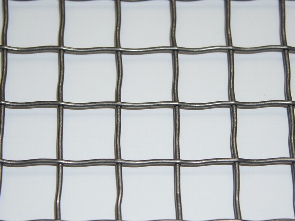
China Reinforcing Wire Mesh for Concrete
Reinforcing wire mesh is a critical component in modern concrete construction, providing tensile strength to compensate for concrete’s inherent weakness in tension. Manufactured from cold-drawn steel wire welded at intersections, this product forms a uniform grid that distributes loads, controls cracking, and enhances structural integrity in slabs, walls, and precast elements. Understanding its specifications, manufacturing variables, and application logic is essential for engineers and procurement teams aiming to minimize failure risks and optimize lifecycle performance.
Material Composition and Wire Properties
The mechanical behavior of reinforcing mesh begins with the base on the chemical composition and tensile properties of the steel wire. Commonly used grades include Q195, Q235, and Q345, each offering different yield strengths and ductility profiles. Q235, with a typical yield strength of 235 MPa and tensile strength of 370–500 MPa, provides a balanced solution for general structural applications. Higher grades like Q345 (yield strength 345 MPa) are selected when increased load capacity or thinner sections are required. Wire diameters typically range from 3 mm to 12 mm, directly influencing the mesh’s load-bearing capacity and stiffness.
Welding Process and Joint Integrity
The strength of the mesh relies heavily on the quality of the welds at wire intersections. Resistance spot welding is the standard method, where electrical current and pressure fuse the wires without adding filler material. Proper welding ensures shear strength at joints that meets or exceeds the base wire’s tensile capacity, preventing slippage under load. Inadequate welding—due to incorrect current, electrode wear, or surface contamination—can create weak points that compromise the mesh’s ability to act as a unified reinforcement system. Manufacturers control welding parameters through automated monitoring to maintain consistent joint strength across large production batches.
Mesh Geometry and Spacing Standards
The grid pattern—defined by wire spacing in both longitudinal and transverse directions—determines how effectively the mesh reinforces the concrete matrix. Standard spacings include 50 mm, 100 mm, 150 mm, and 200 mm, selected based on slab thickness, expected load distribution, and crack control requirements. Tighter spacing (e.g., 50 mm) is used in thin slabs or overlay applications to minimize crack width, while wider spacing (e.g., 200 mm) suits thicker structural slabs where primary load distribution is the goal. The mesh’s cross-sectional area per unit width, calculated from wire diameter and spacing, directly contributes to its tensile reinforcement ratio.
Corrosion Protection and Surface Treatment
In environments exposed to moisture, chlorides, or industrial atmospheres, corrosion of the steel mesh can lead to spalling and loss of bond with concrete. To mitigate this, several surface treatments are applied. Galvanization—either hot-dip or electro-galvanized—provides a zinc coating that acts as a sacrificial barrier. Typical hot-dip galvanized coatings range from 60 to 120 μm, offering extended service life in moderate to aggressive conditions. Alternative options include epoxy-coated wire for high-chloride environments or stainless steel wire (e.g., grade 304 or 316) for permanent installations where maintenance access is limited.
Manufacturing Tolerances and Quality Control
Dimensional accuracy affects placement efficiency and concrete cover consistency. Wire diameter tolerances typically follow ±0.1 mm for precision applications, while welding pitch (spacing between wires) is controlled to ±3 mm to ensure alignment with design reinforcement plans. Flatness and squareness are critical for proper positioning within formwork; excessive curl or twist can lead to inadequate concrete cover or mesh displacement during pouring. Quality control includes visual inspection, weld shear testing, dimensional verification, and coating thickness measurement using magnetic induction or X-ray fluorescence methods.
Standard and Custom Dimensions
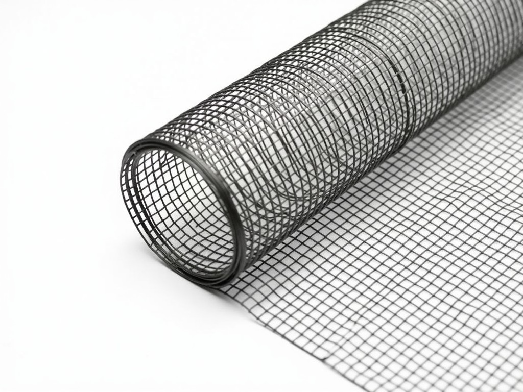
Reinforcing mesh is commonly produced in flat sheets or rolls to suit different handling and placement methods. Standard sheet sizes include 2.4 m × 3.0 m and 2.0 m × 6.0 m, facilitating efficient transportation and overlap during installation. Rolls, typically 0.5 m to 2.0 m wide and up to 50 m long, are preferred for continuous slab pours or wall applications where minimizing lap joints is advantageous. Custom dimensions—such as non-standard widths, lengths, or shaped panels—are available upon request to match specific formwork geometries or reduce field cutting waste.
Applications in Concrete Construction
The selection of reinforcing mesh depends on the structural role it must fulfill. In ground-supported slabs, it controls shrinkage and temperature cracking while distributing point loads from equipment or storage. In suspended slabs, it works alongside rebar to resist bending and shear forces, particularly in thin sections where bar congestion is a concern. For precast elements like wall panels, beams, and hollowcore units, mesh provides uniform reinforcement that simplifies fabrication and improves handling strength. In shotcrete or overlays, fine mesh (e.g., 3 mm wire at 50 mm spacing) enhances adhesion and reduces cracking in thin repair layers.
Comparison of Mesh Configurations
| Configuration | Typical Wire Diameter (mm) | Spacing (mm) | Primary Use Case | Cross-Sectional Area (mm²/m) |
|---|---|---|---|---|
| Light-duty slab mesh | 3.0 | 100 | Residential floors, toppings | 71 |
| Standard structural mesh | 4.0 | 150 | Industrial slabs, parking decks | 168 |
| Heavy-load mesh | 6.0 | 100 | Bridge decks, heavy equipment pads | 377 |
| Overlay/repair mesh | 2.0 | 50 | Thin overlays, spall repair | 63 |
Packaging and Handling Considerations
Proper packaging prevents deformation and corrosion during transit and storage. Sheets are typically bundled in groups of 10–20 units, secured with steel or plastic straps, and wrapped in water-resistant film. Rolls are wound onto rigid cores or suspended on spindles to avoid flat spots. For export shipments, additional protection includes corner guards, moisture-barrier liners, and fumigated wooden pallets compliant with ISPM 15 standards. Handling equipment—such as fork trucks with mesh-specific attachments or roll lifts—should be used to avoid bending or twisting that could compromise placement accuracy.
Customization and Ordering Requirements
To ensure the mesh meets project-specific demands, buyers should provide detailed specifications at quotation stage. Essential information includes: required wire grade and diameter, spacing in both directions, sheet or roll dimensions, preferred surface treatment (e.g., galvanized, epoxy-coated), and any applicable standards (e.g., ASTM A185, BS 4483, EN 10223-2). For custom shapes or cut-to-size panels, a DXF or PDF drawing with tolerances is recommended. Lead times typically range from 2–4 weeks for standard items and 4–6 weeks for customized orders, depending on material availability and production scheduling.
Quality Assurance and Testing Protocols
Reliable performance begins with verifiable quality control. Reputable manufacturers conduct routine testing on raw wire (tensile strength, elongation, bend test), in-process weld shear strength, and final product dimensions. Coating adhesion and thickness are measured using standardized methods such as ASTM D7091 for epoxy or ASTM A90 for zinc. Batch traceability is maintained through material certificates and test reports, which can be provided upon request. Third-party inspection options are available for projects requiring independent validation before shipment.
Product Categories

Send Inquiry
If you are interested in our products, leave your information here and we will be in touch shortly.