Metal Wire For Concrete Source Factory
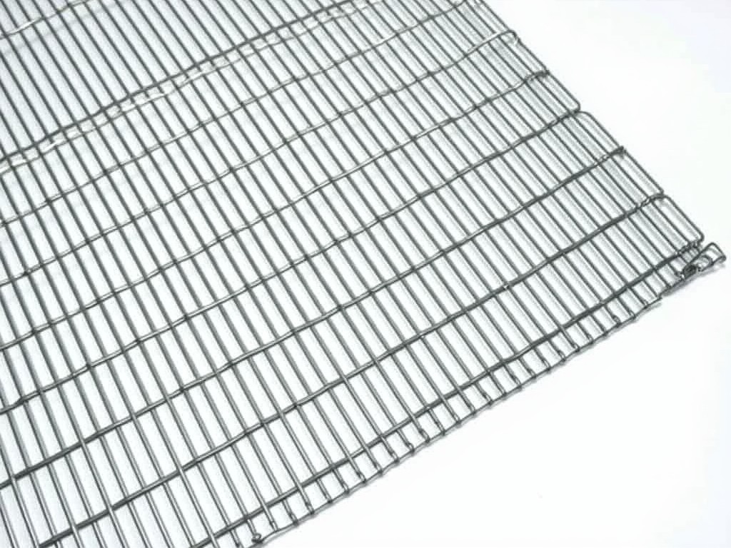
Metal reinforcement wire for concrete is engineered to improve tensile strength, control cracking, and enhance structural integrity in poured concrete elements. Unlike smooth bars, deformed or
Metal Wire for Concrete: Source Factory Specifications and Applications
Metal reinforcement wire for concrete is engineered to improve tensile strength, control cracking, and enhance structural integrity in poured concrete elements. Unlike smooth bars, deformed or indented wire profiles create mechanical interlock with the cement matrix, transferring load more effectively across the composite. This section explains the core functions, material behavior, and selection criteria that industrial buyers evaluate when specifying wire reinforcement for concrete construction.
Material Composition and Mechanical Properties
Concrete reinforcement wire is typically produced from low-carbon steel grades such as SAE 1006 or 1008, with carbon content ranging from 0.06% to 0.10% by weight. This composition ensures sufficient ductility for bending and tying on-site while maintaining a minimum tensile strength of 400 MPa and yield strength of 250 MPa after cold drawing. Surface treatments like galvanization (zinc coating of 20–50 g/m²) or epoxy coating are applied based on environmental exposure requirements to inhibit corrosion without compromising bond performance.
Wire Deformation Patterns and Bond Efficiency
Deformation patterns—such as helical ribs, indentations, or crimped profiles—are rolled into the wire surface during drawing to increase frictional resistance and mechanical anchorage within the concrete. Bond strength tests show that properly deformed wire achieves 20–35% higher pull-out resistance compared to smooth wire of the same diameter. The deformation geometry must balance bond gain with workability; excessively aggressive profiles can cause wire breakage during installation or create stress concentrations that reduce fatigue life.
Diameter Selection and Spacing Guidelines
Wire diameter selection depends on structural demands, slab thickness, and crack control objectives. Common diameters range from 2.0 mm to 5.0 mm, with 3.0 mm and 4.0 mm being most prevalent in residential slabs, precast panels, and shotcrete applications. Spacing is determined by crack width limits and tensile stress distribution; typical grids use 100 mm × 100 mm or 150 mm × 150 mm pitches for ground-supported slabs, while structural elements like beams or walls may require tighter spacing (e.g., 50 mm × 50 mm) to resist concentrated loads.
Manufacturing Process and Quality Control
Production begins with hot-rolled wire rod, which is cleaned, drawn through a series of dies to reduce diameter and increase strength, then passed through deformation rollers to imprint the required pattern. In-line quality checks monitor diameter tolerance (±0.03 mm), deformation height, tensile strength, and elongation (>10% at break). Batch testing includes bend tests (180° around a pin equal to 3× wire diameter) and coating adhesion tests for galvanized or epoxy-coated variants to ensure compliance with ASTM A82, A496, or equivalent standards.
Applications in Concrete Construction
Metal wire reinforcement is selected when distributed crack control and secondary reinforcement are prioritized over primary load-bearing capacity. It is widely used in ground-supported slabs-on-grade where shrinkage and temperature cracking are primary concerns, in precast concrete elements to handle handling stresses, and in shotcrete for tunneling or slope stabilization where conformability to complex shapes is essential. In each case, the wire’s flexibility allows rapid installation while providing uniform crack resistance across large areas.
| Parameter | Typical Range | Notes |
|---|---|---|
| Wire Diameter | 2.0 – 5.0 mm | Selected based on slab thickness and crack width limits |
| Tensile Strength | ≥ 400 MPa | After cold drawing; varies by carbon content and draft |
| Yield Strength | ≥ 250 MPa | Ensures ductility for field bending |
| Elongation at Break | ≥ 10% | Measured in tensile test; indicates ductility |
| Deformation Height | 0.2 – 0.5 mm | Influences bond strength; must not exceed 10% of wire diameter |
| Coating Weight (Galvanized) | 20 – 50 g/m² | Provides corrosion resistance in mild to moderate environments |
Customization and Ordering Considerations
Factories typically offer customization in wire diameter, deformation pattern, coating type, coil weight, and packaging format to match project logistics. Buyers should provide clear specifications including required tensile strength, elongation, bond performance criteria, and environmental exposure conditions. Lead times depend on material availability and coating complexity, with standard cold-drawn wire usually available within 2–3 weeks and coated variants requiring additional 3–5 days. Minimum order quantities often start at 1 ton for standard specifications, with flexibility for trial runs or sample evaluation upon request.
For technical inquiries, specification support, or to request a formal quotation, contact our engineering team directly.
Request Technical Consultation
Product Categories

Send Inquiry
If you are interested in our products, leave your information here and we will be in touch shortly.