Welded Wire Mesh Machine Manufacturer
A welded wire mesh machine is a precision industrial system designed to automate the production of welded wire mesh panels and rolls from steel wire. The machine performs wire feeding, straightening,
Welded Wire Mesh Machine Manufacturer
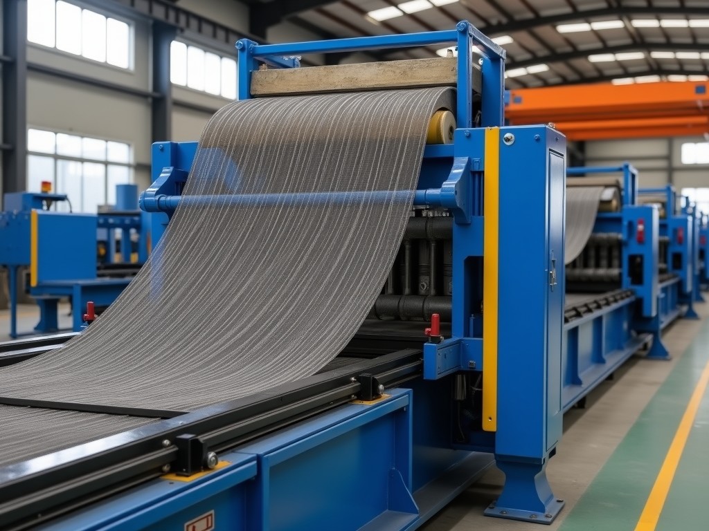
A welded wire mesh machine is a precision industrial system designed to automate the production of welded wire mesh panels and rolls from steel wire. The machine performs wire feeding, straightening, cross-wire positioning, resistance welding, and cutting in a synchronized sequence. Output specifications depend on wire diameter, mesh opening size, welding speed, and panel dimensions. Manufacturers engineer these systems for continuous operation in high-volume production environments where dimensional consistency and weld integrity are critical.
Selecting a welded wire mesh machine requires evaluating technical capabilities beyond basic output rates. Key considerations include wire tension control accuracy, weld nugget size consistency, programmable pattern flexibility, and maintenance accessibility. Industrial buyers prioritize machines that minimize scrap, reduce changeover time, and maintain tight tolerances over extended production runs. The following sections detail the technical attributes that define machine performance and suitability for specific applications.
Core Technical Specifications
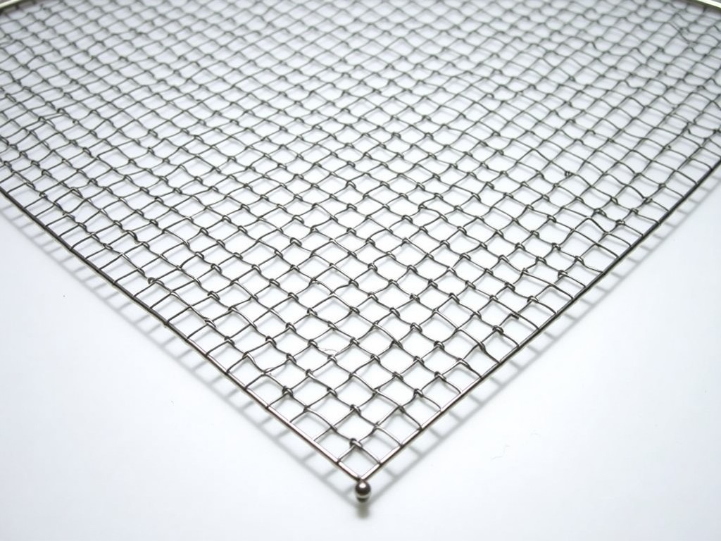
Welded wire mesh machines are classified by their wire handling capacity and welding technology. Entry-level systems typically process wire diameters from 2.0 mm to 5.0 mm, while heavy-duty models accommodate 6.0 mm to 12.0 mm or larger. Welding is performed via resistance welding, where precise current, pressure, and time parameters create fused joints at wire intersections. Mesh opening sizes range from 25 mm x 25 mm for fine filtration applications to 200 mm x 200 mm or more for concrete reinforcement and fencing.
Machine speed is measured in welds per minute or linear meters per minute, depending on configuration. A typical mid-range machine produces 60–90 welds per minute with 4.0 mm wire at 50 mm openings. High-speed models exceed 150 welds per minute through multi-head welding stations and optimized wire feed synchronization. Drive systems use servo motors for precise wire positioning, while pneumatic or hydraulic systems apply welding pressure. Control systems employ PLCs with touchscreen interfaces for pattern programming, production monitoring, and fault diagnostics.
Material Compatibility and Wire Preparation
The machine must accommodate the metallurgical properties of the input wire. Low-carbon steel wire (e.g., SAE 1006–1010) is most common due to its weldability and cost-effectiveness. Galvanized wire requires careful parameter adjustment to avoid zinc vaporization and porous welds; some machines include pre-weld scraping or inert gas shielding. Stainless steel wire (e.g., 304, 316) demands higher welding currents and precise thermal control to prevent cracking and maintain corrosion resistance. Wire tensile strength and elongation values directly influence feeding stability and weld quality.
Wire preparation includes decoiling, straightening, and de-twisting. Machines incorporate adjustable straightening rollers to remove coil memory and ensure linear feed. Tension control systems maintain consistent wire pull force, typically within ±5%, to prevent sagging or over-tensioning that causes misalignment. Some systems integrate lubricators or coating applicators for specialized wire types. Wire diameter sensors and break detectors halt production automatically to prevent defects and equipment damage.
Changeover between wire sizes or mesh patterns requires adjusting multiple parameters: wire guide positions, roller gaps, welding electrodes, and welding schedules. Quick-change tooling systems reduce downtime by enabling rapid exchange of feeding guides, welding heads, and cutting blades. Manufacturers design modular wire handling units to support frequent product transitions without full recalibration. Lubrication points, electrode wear indicators, and wire path accessibility are engineered for efficient maintenance.
Welding Technology and Process Control
Resistance welding in mesh machines relies on precise control of three variables: welding current (kA), weld time (cycles), and electrode force (kN). The welding current generates heat at the wire cross-point, melting a small volume of metal to form a nugget. Electrode force ensures intimate contact and expels oxides. Imbalanced parameters cause defects: insufficient heat leads to weak nuggets, excessive heat causes burn-through or wire weakening, and uneven force results in asymmetric welds. Machines monitor these parameters in real time via closed-loop feedback.
Electrode geometry and material significantly affect weld consistency. Copper alloy electrodes with specific contours (e.g., truncated cone, flat face) are selected based on wire diameter and material. Electrode wear compensation algorithms adjust welding current over time to maintain nugget size as electrodes erode. Some systems include automatic electrode dressing or rotation to extend service life. Cooling systems, typically water-cooled electrodes and transformers, prevent overheating during continuous operation.
Advanced machines feature adaptive welding control that responds to variations in wire resistance, surface condition, or ambient temperature. Integrated sensors measure pre-weld resistance at each joint and adjust current accordingly. Production data logging records weld count, average current, fault codes, and cycle times for quality traceability. Machines may include statistical process control (SPC) functions to alert operators to drift in weld parameters before defects occur. These capabilities reduce scrap and support compliance with quality standards.
Mesh Pattern Flexibility and Production Modes
Welded wire mesh machines produce various patterns beyond standard square grids. Rectangular openings (e.g., 50 mm x 100 mm) are common in concrete reinforcement where load directionality matters. Offset or staggered patterns increase shear resistance in structural applications. Some machines create trapezoidal or hexagonal openings for specialized filtration or architectural screens. Pattern flexibility depends on the cross-wire feeding mechanism: drop-through systems limit patterns to perpendicular grids, while swing-arm or carousel feeders enable angular or complex layouts.
Panel versus roll production defines machine configuration. Panel machines cut and stack finished mesh to specific lengths (e.g., 2.4 m x 1.2 m) for direct use in construction. Roll machines produce continuous lengths wound onto spools for later cutting or further processing. Hybrid systems offer both modes with adjustable cut-off mechanisms. Production mode affects wire handling: panel machines require precise length measurement and stacking systems, while roll machines need consistent tension and spool synchronization to avoid telescoping or snags.
Changeover between patterns or production modes involves reprogramming the PLC, adjusting wire guides, and potentially changing welding heads or cutting tools. Machines with stored recipe systems allow operators to recall settings for frequent products via touchscreen selection. Batch counters, length encoders, and photo-eye sensors ensure accurate panel counting and roll metering. Some systems integrate stacking robots or conveyor transfers for fully automated downstream handling. The ability to switch quickly between products directly impacts equipment utilization and responsiveness to customer orders.
Typical Technical Values
| Parameter | Typical Range | Notes |
|---|---|---|
| Wire Diameter Range | 2.0 mm – 12.0 mm | Dependent on model; larger diameters require higher welding current | Mesh Opening Size | 25 mm x 25 mm – 200 mm x 200 mm | Custom openings available; non-square patterns possible with advanced feeders |
| Welding Speed | 40 – 180 welds/minute | Varies with wire size, opening, and number of welding heads |
| Production Width | 500 mm – 3000 mm | Maximum width limited by machine frame and wire handling capacity |
| Control System | PLC with HMI touchscreen | Stores recipes, monitors faults, logs production data |
| Power Supply | 3-phase, 380V–480V, 50/60 Hz | Typical industrial voltage; transformer size scales with welding current |
Applications and Industry Fit
Welded wire mesh serves as a fundamental reinforcement material in concrete construction. The mesh distributes tensile stresses, controls cracking, and improves impact resistance in slabs, walls, and precast elements. Machine-produced mesh ensures consistent wire spacing and weld strength, which directly affects structural performance. Unlike manually tied mesh, automated production eliminates human variability in spacing and tying tightness, resulting in predictable load distribution and reduced labor costs on-site.
In fencing and security applications, welded wire mesh provides a rigid barrier with uniform opening sizes that prevent climbing or intrusion. The weld integrity ensures the mesh maintains shape under tension and impact, unlike woven alternatives that can unravel. Galvanized or PVC-coated mesh produced by these machines offers corrosion resistance for outdoor use. Mesh opening size is selected based on the threat level: small openings deter animal intrusion, while larger openings provide visibility and wind resistance for perimeter security.
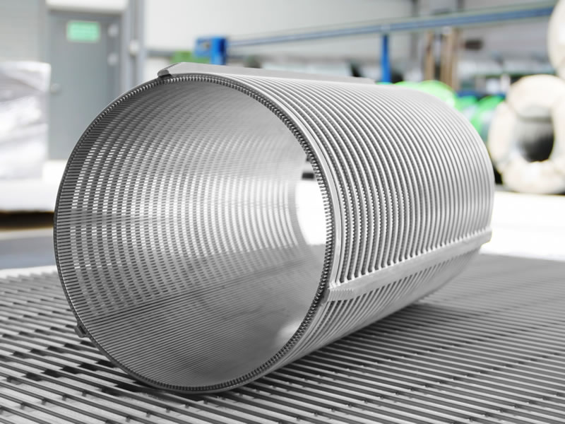
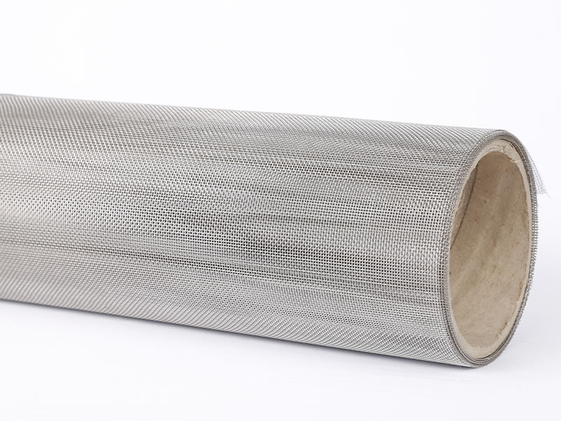
Industrial filtration and screening systems rely on welded wire mesh for precise particle separation. The rigid, non-deformable openings maintain consistent flow characteristics under pressure. Applications include aggregate screening, coal preparation, food processing, and chemical filtration. Mesh material and opening size are matched to the particulate size distribution and flow rate. Machines producing fine mesh with tight tolerances enable high-efficiency separation where woven screens would blind or deform. The ability to produce custom patterns (e.g., tapered openings) further enhances performance in specialized screening equipment.
Quality Control and Manufacturing Considerations
Machine quality begins with frame rigidity and component alignment. The welding station must maintain precise perpendicularity between longitudinal and cross-wire feeds to ensure square openings. Frames are stress-relieved after welding to prevent distortion that accumulates over time. Linear guides and bearings for wire feeding systems are selected for low friction and high wear resistance. Regular verification of wire path alignment using dial indicators or laser systems is recommended during installation and maintenance.
Weld quality is assessed through destructive and non-destructive methods. Tensile shear testing of welded joints verifies nugget strength against material specifications. Metallographic cross-sections examine nugget size, penetration, and absence of cracks or inclusions. Resistance measurements across welds detect inconsistencies in conductivity that may indicate poor fusion. Production machines often include automated weld inspection via cameras or sensors that detect missing welds, misalignment, or gross defects at speed.
Preventive maintenance schedules focus on wear-prone components: welding electrodes, wire guides, straightening rollers, and cutting blades. Electrode wear is tracked by monitoring welding current required to maintain nugget size. Wire guide grooves are inspected for abrasion that could cause wire scoring or deviation. Hydraulic or pneumatic systems are checked for leaks and pressure consistency. Lubrication of linear bearings, gearboxes, and chains follows manufacturer intervals. Maintenance logs help predict component life and optimize spare part inventory.
Customization and Integration Options
Manufacturers offer configuration options to match machine capabilities to specific production needs. Wire handling systems can be adapted for coiled wire, pay-off reels, or straight wire feeding. Welding head count can be increased to boost output for fine mesh or reduced for heavy wire where single-head welding suffices. Cut-off mechanisms include flying shears for roll production or stationary shears for panel machines. Stacking systems range from simple conveyors to robotic palletizers for finished panels.
Integration with upstream and downstream equipment improves line efficiency. Pay-off systems with automatic splice detection minimize downtime during wire changeover. Pre-straighteners or tension regulators upstream ensure optimal wire condition enters the welding zone. Downstream, mesh can be directed to bending machines for fabricating cages, coating lines for galvanizing or painting, or packaging equipment for bundling. Communication protocols (e.g., Modbus TCP) allow the mesh machine to synchronize speed with connected equipment based on real-time load.
Control system customization includes multi-language interfaces, remote monitoring capabilities, and data export for MES or ERP integration. Recipe management systems store hundreds of product configurations with parameters for wire size, opening, weld schedule, and length. User access levels prevent unauthorized changes to critical settings. Some machines include energy monitoring to track power consumption per kilogram of mesh produced, supporting operational cost analysis. Safety features such as light curtains, emergency stops, and interlocked guards are configured to meet regional safety standards.
For detailed technical consultation, customization options, or to discuss your specific welded wire mesh production requirements, contact our engineering team. We provide application-specific recommendations based on wire specifications, target output, and integration needs.
Product Categories

Send Inquiry
If you are interested in our products, leave your information here and we will be in touch shortly.