Duplex Stainless Steel Filler Wire
Duplex stainless steel filler wire is engineered to match the microstructure and corrosion resistance of duplex base metals during welding. It contains balanced austenitic-ferritic phases, typically
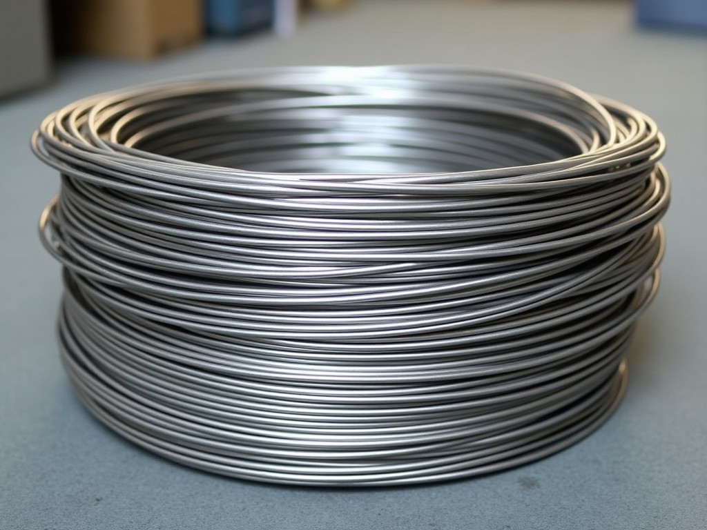
Duplex Stainless Steel Filler Wire
Duplex stainless steel filler wire is engineered to match the microstructure and corrosion resistance of duplex base metals during welding. It contains balanced austenitic-ferritic phases, typically 22% chromium, 5-6% nickel, and 3% molybdenum, with nitrogen additions to stabilize the austenite fraction. This composition ensures weld metal strength exceeding 620 MPa and pitting resistance equivalent numbers (PREN) above 34, critical for maintaining integrity in chloride-exposed environments.
Microstructural Stability in Weld Metal
Achieving consistent ferrite-austenite balance in the weld deposit requires precise control of nickel equivalent and chromium equivalent ratios during wire manufacturing. Deviations can lead to excessive ferrite, reducing toughness, or insufficient ferrite, increasing susceptibility to stress corrosion cracking. Our filler wire is produced with tight chemical tolerances—nickel held within ±0.15% and nitrogen controlled to ±0.02%—to ensure the weld metal maintains 30-50% ferrite content after solidification, as verified by magnetic induction testing per ASTM E835.
This microstructural control directly impacts mechanical performance: yield strength remains uniform across the weld zone, elongation exceeds 25%, and Charpy V-notch impact values at -40°C stay above 40 J. These properties are not incidental; they result from suppressing harmful intermetallic phases like sigma and chi through optimized cooling rates during wire drawing and annealing. Buyers should verify ferrite prediction models (e.g., WRC-1992) are applied when selecting wire for specific duplex grades such as 2205 or 2507.
Corrosion Resistance Matching Base Metal
The filler wire’s alloy design ensures the weld metal’s pitting and crevice corrosion resistance equals or exceeds that of the duplex base metal. Critical pitting temperature (CPT) tests in ferric chloride solution typically show values above 35°C for 2205-compatible wire, matching ASTM G48 Method A requirements. This is achieved not by over-alloying—which risks hot cracking—but by maintaining the precise Cr-Mo-N balance that repassivates passive films rapidly after chloride attack.
In sour service environments (H₂S exposure), the wire’s low carbon content (<0.03%) and restricted sulfur levels (<0.005%) minimize sulfide stress cracking risk. Unlike overmatched austenitic fillers, duplex-compatible wire avoids creating galvanic couples at the weld interface, which could accelerate localized corrosion. For submerged marine applications, welds made with this wire demonstrate equivalent mass loss rates in alternating salt spray tests compared to the base metal after 1000 hours exposure.
Manufacturing Process Controls
Filler wire quality begins with raw material selection: electrolytic chromium, nickel cathodes, and ferromolybdenum with verified low trace elements. Vacuum induction melting ensures homogeneous distribution of nitrogen and prevents oxide inclusions that could act as crack initiation sites. The molten alloy is cast into electrodes, then drawn through diamond dies in multiple passes—each reduction step followed by solution annealing at 1050°C to relieve stresses and stabilize microstructure.
Final processing includes precision leveling to maintain cast and helix within ±0.5mm over 1.5m lengths, critical for smooth wire feeding in automated welding systems. Surface contaminants are removed via alkaline cleaning and electrolytic polishing, achieving a surface roughness below 0.8μm Ra. Each batch undergoes spectrometer verification (OES) for chemistry and ferroscan testing for ferrite content before packaging. These steps prevent weld defects like porosity or lack of fusion caused by inconsistent wire diameter or surface contaminants.
Diameter Selection and Welding Parameters
Filler wire diameter directly influences deposition rate, bead geometry, and heat input. For GMAW (MIG) welding of duplex stainless steel, 0.9mm and 1.2mm diameters are most common: 0.9mm suits thin-walled tubes (<6mm) requiring low heat input to avoid intermetallic formation, while 1.2mm is used for structural plates >10mm where higher deposition improves productivity. Using 1.6mm wire on thin sections risks burn-through and excessive ferrite due to slower travel speeds needed to manage the larger melt pool.
Recommended shielding gas is 98% Argon/2% CO₂ or 90% He/7.5% Ar/2.5% CO₂ to balance arc stability and oxide reduction. Voltage typically ranges 22-28V for 0.9mm wire and 24-30V for 1.2mm, with amperage between 90-140A and 130-180A respectively. Travel speed should maintain heat input between 1.0-1.5 kJ/mm to prevent sigma phase formation; exceeding this range reduces impact toughness by up to 30%. Wire stick-out should remain 12-15mm to ensure consistent current transfer and minimize spatter.
Quality Assurance and Testing
Every spool undergoes full traceability from raw material lot to final packaging. Chemical analysis is performed per ASTM A751 using optical emission spectroscopy, with results certified to EN 10204 3.1 standards. Ferrite content is measured both chemically (via WRC-1992) and magnetically to confirm consistency. Mechanical properties are validated through all-weld metal tensile tests per ISO 6892-1 and Charpy impact tests at -46°C per ISO 9016, ensuring batch-to-batch repeatability.
Surface quality is inspected under 10x magnification for drawing marks, grooves, or contamination that could cause wire feeding issues. Diameter tolerance is held to ±0.02mm for 0.9mm and ±0.03mm for 1.2mm wire, verified by laser micrometry at 100mm intervals along the spool. Hydrostatic testing of sealed spools ensures moisture protection during transit, preventing hydrogen pickup that could compromise weld integrity in high-strength applications.
Applications in Corrosive Environments
Duplex filler wire is selected when base metal resistance to chloride-induced pitting and stress corrosion cracking is essential. In offshore oil and gas, it welds duplex pipelines and risers exposed to seawater and H₂S, where overmatching with austenitic filler (e.g., ER309L) would create a galvanic cell accelerating corrosion at the weld toe. The wire’s matching PREN ensures uniform corrosion rates across the joint, extending service life in splash zones and subsea umbilicals.
In desalination plants, duplex filler wire welds heat exchanger tubes and brine headers subjected to fluctuating temperatures and high chloride concentrations. Unlike austenitic alternatives, it avoids sigma phase formation during post-weld heat treatment, preserving ductility in multi-pass welds. Chemical processing facilities use it for reactors handling mixed acids—where its molybdenum content resists reducing agents like sulfuric acid while chromium withstands oxidizing conditions such as nitric acid—without requiring post-weld solution annealing.
Comparison with Alternative Filler Metals
| Property | Duplex Filler Wire (2209) | Austenitic Filler (ER309L) | Super Duplex Filler (2594) |
|---|---|---|---|
| Typical PREN | 34-36 | 24-26 | >40 |
| Yield Strength (MPa) | 550-650 | 350-450 | 650-750 |
| Ferrite Content (%) | 30-50 | 0-5 (fully austenitic) | 40-55 |
| CPT (°C) in FeCl₃ | 30-35 | <15 | 35-40 |
| Risk of Hot Cracking | Low (with proper NiEq/CrEq) | Very Low | Moderate (requires strict Ni control) |
The table shows duplex filler wire offers a balanced alternative: higher strength and corrosion resistance than ER309L without the cracking sensitivity of 2594 super duplex wire. ER309L’s lack of ferrite eliminates sigma risk but leaves the weld vulnerable to pitting in chlorides—its PREN of 25 means it corrodes up to 3x faster than 2205 base metal in equivalent conditions. Meanwhile, 2594 filler provides superior PREN but demands tighter process control to avoid Laves phase formation, increasing weld complexity and cost. For most duplex 2205 applications, 2209 filler wire provides the optimal trade-off between performance and weldability.
Spool Configurations and Handling
Filler wire is packaged to prevent contamination and deformation during transit and storage. Standard spools include BS300 (15kg), BS450 (25kg), and drum packs (200kg) for high-volume automated welding. Each spool features a anti-static polypropylene liner to minimize particulate adhesion, with outer corrugated cardboard protection. Inner diameter is 52mm for BS300/BS450 spools to fit standard wire feeders, while drum packs use 360mm barrels with conical outlets to prevent tangling during high-speed payoff.
Storage recommendations: keep in original packaging at 10-30°C with relative humidity below 60% to prevent moisture absorption. Avoid direct sunlight exposure, which can degrade polymer liners over time. Before use, inspect for surface discoloration or oxidation—light straw coloring is acceptable from annealing, but dark blue or black indicates overheating during storage and warrants rejection. Wire should be fed directly from the spool without rewinding to preserve cast and helix characteristics critical for stable arc performance.
Ordering Information and Technical Support
To ensure correct filler wire selection, provide the base metal duplex grade (e.g., 2205, 2507), welding process (GMAW, GTAW, SAW), material thickness, and service environment (chloride concentration, temperature, H₂S presence). For non-standard diameters or spool sizes, specify required tolerances and packaging needs—custom leveling or helicity adjustments are available upon request. All orders include material test reports (MTR) with actual chemistry, ferrite content, and mechanical test results from the weld deposit.
Technical datasheets detailing welding parameters, microstructure predictions, and corrosion test data are available for download. Our metallurgists can review WPS documentation to confirm filler wire compatibility with your specific joint design and post-weld heat treatment schedule. For critical applications, we recommend conducting a procedure qualification record (PQR) using the actual filler wire lot to validate mechanical and corrosion properties before production welding begins.
More Products

Send Inquiry
If you are interested in our products, leave your information here and we will be in touch shortly.