Welding Stainless Steel With Mild Steel Wire
Joining stainless steel to mild steel using mild steel filler wire presents specific metallurgical challenges that directly impact joint integrity, corrosion resistance, and long-term performance.
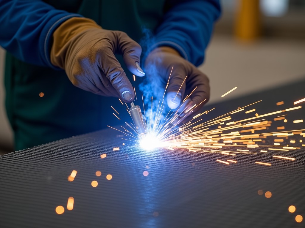
Welding Stainless Steel with Mild Steel Wire: Technical Considerations
Joining stainless steel to mild steel using mild steel filler wire presents specific metallurgical challenges that directly impact joint integrity, corrosion resistance, and long-term performance. This process is common in fabrication where dissimilar metals must be joined, such as attaching mild steel brackets to stainless steel tanks or piping systems. Understanding the underlying mechanisms is essential for engineers specifying welding procedures and procurement teams evaluating consumable suitability.
The primary concern arises from the formation of a martensitic or brittle intermetallic zone at the fusion boundary due to carbon diffusion from the mild steel wire into the stainless steel base metal. This phenomenon reduces ductility and increases susceptibility to cracking, particularly under thermal cycling or mechanical stress. Additionally, the chromium content in the stainless steel base metal can be locally depleted near the weld, compromising its passive oxide layer and reducing corrosion resistance in the heat-affected zone (HAZ).
To mitigate these risks, welding procedures must carefully control heat input, interpass temperature, and filler wire chemistry. Using mild steel wire (typically ER70S-6) requires precise parameter optimization to minimize carbon pickup and maintain adequate fusion without excessive base metal dilution. Preheating is generally not recommended for austenitic stainless steels, as it can exacerbate sigma phase formation; instead, low-heat-input techniques such as pulsed MIG or TIG are preferred.
Metallurgical Behavior of Dissimilar Metal Joints
When mild steel wire is used to weld stainless steel, the resulting weld metal contains elevated carbon levels (typically 0.08–0.12%) compared to the base stainless steel (usually <0.03% for 304L/316L). This carbon enrichment promotes the formation of chromium carbides at grain boundaries during cooling, especially if the weld lingers in the 450–850°C temperature range. The consequence is intergranular corrosion susceptibility and reduced toughness in the weld metal.
Simultaneously, iron from the mild steel wire dilutes the nickel and chromium content in the weld pool, shifting the microstructure toward ferrite or even martensite depending on the Cr_eq/Ni_eq ratio. A weld with insufficient nickel equivalent may lose austenitic stability, leading to magnetic response and reduced toughness at low temperatures. These changes are measurable via ferrite number (FN) testing and can be predicted using Schaeffler or DeLong diagrams.
The heat-affected zone (HAZ) in the stainless steel base metal also experiences thermal cycling that can precipitate sigma phase if exposed to 600–900°C for prolonged periods, particularly in duplex or super austenitic grades. Sigma phase embrittlement reduces impact strength and is irreversible without solution annealing. Therefore, limiting time in this critical temperature range is crucial for preserving mechanical properties.
Recommended Welding Procedures and Parameters
To minimize adverse metallurgical effects, welding should be performed using short-circuit or pulsed MIG (GMAW) with argon-based shielding gases. A common shielding gas mix is 98% argon / 2% CO₂, which provides adequate arc stability while reducing oxidation and spatter compared to pure CO₂. For thinner sections (<3 mm), TIG (GTAW) with pure argon offers superior control over heat input and bead geometry.
Voltage and amperage must be kept low to limit penetration and base metal dilution. Typical parameters for 0.8–1.2 mm ER70S-6 wire on 3 mm stainless steel sheet: 18–22 V, 80–120 A, travel speed 12–18 cm/min. Higher currents increase dilution and carbon pickup, increasing the risk of hot cracking and reducing corrosion resistance. Interpass temperature should not exceed 150°C to avoid cumulative thermal effects.
Joint design should favor lap or T-fillet configurations over butt joints when possible, as they allow better control of penetration depth and reduce the volume of dissimilar metal mixing. Edge preparation should be minimal—square edges or light chamfer (<1 mm) are sufficient. Cleanliness is critical: all oxides, oils, and contaminants must be removed from both base metals prior to welding using stainless steel wire brushes or solvent wiping to prevent porosity and inclusions.
Post-Weld Treatment and Inspection Requirements
After welding, the joint should undergo visual inspection for cracks, undercut, and incomplete fusion. Dye penetrant testing (PT) is recommended for detecting surface-breaking flaws in the weld and HAZ, especially in applications subject to fatigue or cyclic loading. For thicker sections (>6 mm), radiographic testing (RT) or ultrasonic testing (UT) may be required to assess internal defects, though sensitivity to porosity in carbon steel welds can limit RT effectiveness.
Corrosion resistance of the weld zone can be assessed using accelerated testing such as salt spray (ASTM B117) or copper sulfate-sulfuric acid etch (ASTM A262 Practice E) to detect intergranular attack. However, these tests are indicative rather than definitive for field performance. In critical applications, electrochemical potentiodynamic reactivation (EPR) testing provides a quantitative measure of sensitization susceptibility.
Post-weld heat treatment is generally not advised for austenitic stainless steels welded with mild steel wire, as it can promote sigma phase formation. Instead, stress relief—if required by design code—should be limited to temperatures below 400°C to avoid sensitization. Mechanical properties such as tensile strength and elongation should be verified per applicable standards (e.g., ASME Section IX, ISO 15614-1), with typical tensile strength ranging from 400–550 MPa and elongation >20% in the weld metal when proper procedures are followed.
Applications and Limitations in Industrial Fabrication
This welding method is commonly employed in non-critical structural attachments where cost savings outweigh performance demands, such as fastening mild steel supports to stainless steel ductwork, conveyor frames, or architectural trim. It is also used in temporary fixtures or jigs where the weld is not expected to endure corrosive environments or dynamic loads. In these cases, the reduced corrosion resistance and toughness of the joint are acceptable trade-offs for simplified inventory and lower filler cost.
However, it is unsuitable for pressure vessels, food processing equipment, chemical piping, or marine environments where long-term corrosion resistance and hygienic performance are required. The chromium-depleted zone and potential for carbide precipitation create preferential paths for pitting and stress corrosion cracking (SCC), particularly in chloride-containing atmospheres. For such applications, matching or over-alloyed filler metals (e.g., ER308L, ER309L, ER316L) are mandatory to maintain base metal properties.
Fabricators should conduct a risk assessment based on service conditions: temperature, exposure media, stress levels, and design life. If the joint will be exposed to wet/dry cycling, temperatures above 100°C, or tensile stresses exceeding 20% of yield strength, alternative joining methods—such as mechanical fastening with isolation sleeves or transition joints using nickel-based fillers—should be evaluated. Documentation of welding procedure specification (WPS) and procedure qualification record (PQR) is essential for traceability and compliance.
For technical consultation on welding procedure selection, parameter optimization, or filler material suitability for dissimilar metal joints, contact our engineering team to review your specific application requirements.
Request Technical Guidance

More Products

Send Inquiry
If you are interested in our products, leave your information here and we will be in touch shortly.