Oem Fan Guard Cover For Air Conditioner
An OEM fan guard cover for air conditioner is a safety and performance-critical component designed to protect the condenser or evaporator fan blades while maintaining optimal airflow. It is
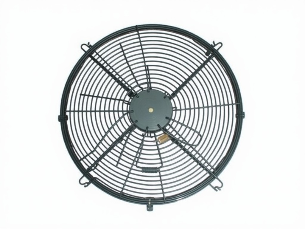
OEM Fan Guard Cover for Air Conditioner
An OEM fan guard cover for air conditioner is a safety and performance-critical component designed to protect the condenser or evaporator fan blades while maintaining optimal airflow. It is engineered to match the exact specifications of the original equipment manufacturer, ensuring seamless integration into HVAC systems without requiring modification to mounting points or fan clearances. This component is not merely a protective barrier; its geometric design directly influences system efficiency, noise levels, and long-term reliability by preventing debris ingress and minimizing vibration-induced wear.
Unlike generic aftermarket guards, OEM specifications dictate precise wire spacing, frame thickness, and mounting flange geometry to satisfy UL/CSA safety standards and manufacturer-specific performance tolerances. Deviations in these parameters can reduce airflow by 5–15%, increase static pressure drop, and compromise fan motor lifespan due to uneven loading. Procurement engineers must verify dimensional accuracy against the OEM part number, not just visual similarity, to avoid unintended system derating.
Material Selection and Structural Properties
Fan guard covers are typically fabricated from either cold-rolled steel (CRS) with zinc plating or stainless steel (AISI 304 or 316), selected based on environmental exposure and corrosion resistance requirements. CRS with zinc plating offers a cost-effective solution for indoor or mildly corrosive outdoor environments, providing 5–10 years of service life under ASTM B117 salt spray testing at 96 hours. Stainless steel variants are specified for coastal installations, industrial chemical exposure, or high-humidity climates where chloride-induced pitting must be avoided.
Wire diameter commonly ranges from 2.0mm to 3.5mm, with spacing between 12mm and 25mm center-to-center, calibrated to prevent finger penetration (per ISO 13857) while minimizing airflow obstruction. The frame is usually formed from 1.2mm–1.8mm thick strip steel, bent into a U-channel or L-flange configuration for rigidity and ease of mounting. Spot welding or robotic MIG welding is used at junctions to ensure consistent joint strength without distorting the guard’s planar geometry.
Dimensional Customization and Mounting Interfaces
OEM fan guard covers are not standardized commodities; each is defined by the specific air conditioner model’s fan diameter, mounting hole pattern, and clearance requirements to the coil or housing. Critical dimensions include outer diameter (OD), inner diameter (ID) if applicable, flange width, hole diameter, hole pitch, and depth from mounting plane to fan blade tip. These are typically derived from the OEM’s CAD data or reverse-engineered from physical samples when documentation is unavailable.
Mounting interfaces vary significantly: some utilize snap-in clips molded into the guard’s flange, others rely on self-tapping screws through pre-drilled holes, and heavy-duty units may employ bolted flanges with nylon washers to prevent galvanic corrosion. Tolerances are held to ±0.5mm for hole positions and ±1.0mm for overall diameter to ensure the guard does not rub against rotating blades or create air turbulence. Custom tooling is often required for low-volume OEM replacements, making prototype validation essential before full production.
Performance Impact and System Integration
The aerodynamic design of the fan guard cover directly affects the system’s static pressure drop and sound power level. A poorly designed guard can increase pressure drop by 10–20 Pa at nominal airflow, forcing the fan motor to draw 5–8% more power to maintain cooling capacity. CFD analysis shows that wire spacing below 15mm significantly increases turbulence-induced noise, particularly in the 500–2000 Hz range, which is perceptible as increased hum or buzz in quiet residential or office environments.
Conversely, guards with optimized wire geometry — such as tapered wires or oval cross-sections — can reduce pressure drop by up to 15% compared to standard round wire designs while maintaining equivalent protection. OEM specifications often include these refinements, which are absent in generic replacements. Engineers evaluating replacement guards should request pressure drop test data at the system’s rated airflow (e.g., 600–1200 CFM for residential condensers) rather than relying solely on visual inspection.
Quality Control and Manufacturing Considerations
Quality assurance for OEM fan guard covers begins with incoming material inspection, verifying zinc coating thickness (min. 8µm for CRS) or stainless steel composition via XRF. Dimensional checks are performed using CMM or optical comparators on first-off samples, focusing on critical features: hole location, flange flatness, and wire spacing uniformity. Visual inspection under 10x magnification ensures welds are free of spatter, cracks, or undercut that could initiate fatigue failure under cyclic vibration.
Functional validation includes a rotational clearance test — where the guard is installed and the fan is run at maximum RPM to confirm zero blade contact — and a salt spray test per ASTM B117 for corrosion-resistant variants. Packaging is designed to prevent deformation during transit: guards are nested in die-cut cardboard trays with polyethylene spacers and shipped in double-wall cartons. For export, moisture-barrier bags and desiccant packs are added to prevent condensation-induced staining on plated surfaces.
Applications in HVAC Systems
Fan guard covers are deployed in both condenser and evaporator units across residential, commercial, and light industrial air conditioning systems. In condensers, they protect the outdoor fan from leaves, twigs, and urban debris while maintaining airflow across the finned coil — critical for heat rejection efficiency. In evaporators, particularly in ducted or ceiling-mounted units, they prevent accidental contact during maintenance and stop loose insulation or filter media from being drawn into the fan blades.
In variable refrigerant flow (VRF) systems and rooftop units (RTUs), where multiple fans operate in close proximity, guard design must account for inter-fan airflow interference and vibration harmonics. OEM specifications for these applications often include reinforced frames or asymmetric wire spacing to mitigate mode-shaped vibrations that could lead to resonant failure. Distributors serving HVAC contractors prioritize guards that match the OEM’s noise and vibration test criteria, not just physical dimensions.
| Parameter | Typical Range / Specification | Notes |
|---|---|---|
| Material | Cold-rolled steel with zinc plating, AISI 304/316 stainless steel | Zinc plating: min. 8µm thickness; Stainless steel for marine/industrial use |
| Wire Diameter | 2.0mm – 3.5mm | Balances protection vs. airflow obstruction |
| Wire Spacing (Center-to-Center) | 12mm – 25mm | Must comply with ISO 13857 finger safety limits |
| Frame Thickness | 1.2mm – 1.8mm | U-channel or L-flange formed for rigidity |
| Mounting Hole Diameter | 4.0mm – 6.0mm | Matches self-tapping screws or bolts |
| Mounting Hole Pitch | 25mm – 100mm (variable pattern) | Must match OEM flange or bracket locations |
| Overall Diameter Tolerance | ±1.0mm | Prevents blade rub or air turbulence |
| Pressure Drop at 800 CFM | 10–25 Pa (OEM-optimized: <15 Pa) | Measured per AMCA 210; impacts fan power consumption |
| Salt Spray Resistance (ASTM B117) | 96 hours (zinc), 500+ hours (304 SS), 1000+ hours (316 SS) | Indicates corrosion life in outdoor environments |
For OEM fan guard cover procurement, engineers should provide the air conditioner model number, fan diameter, mounting hole pattern, and environmental conditions (indoor/outdoor, coastal/industrial) to enable accurate quoting. Material choice, wire geometry, and flange design are determined based on these inputs to ensure compliance with safety standards and system performance requirements. Samples are available for validation prior to production approval, particularly for custom or low-volume replacements.
To initiate a technical inquiry or request a quotation for OEM fan guard covers tailored to your specific air conditioning equipment, please contact our engineering team. We will review your specifications, confirm material suitability, and provide dimensional drawings for approval before tooling.
More Products

Send Inquiry
If you are interested in our products, leave your information here and we will be in touch shortly.