Oem Perforated Aluminum Composite Panel
Perforated aluminum composite panels (ACPs) combine the structural efficiency of aluminum skins with a thermoplastic or mineral-filled core, modified through precision perforation to achieve specific
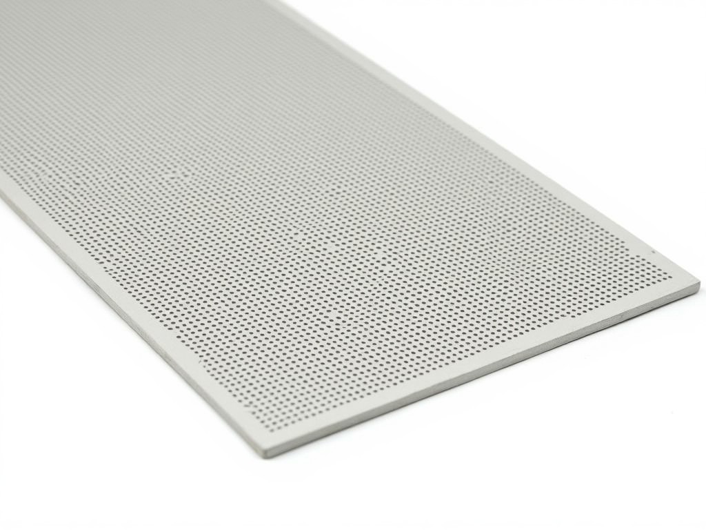
OEM Perforated Aluminum Composite Panel
Perforated aluminum composite panels (ACPs) combine the structural efficiency of aluminum skins with a thermoplastic or mineral-filled core, modified through precision perforation to achieve specific functional and aesthetic outcomes. For OEM applications, these panels are engineered to meet exacting dimensional, mechanical, and surface finish requirements dictated by downstream assembly processes. The perforation pattern is not merely decorative; it directly influences airflow dynamics, acoustic transmission loss, light diffusion, and surface area for coating adhesion or mechanical fastening.
Material selection begins with the alloy composition of the outer skins—typically 3003 or 5005 aluminum for formability and corrosion resistance—bonded to a low-density polyethylene (PE) or fire-retardant (FR) core. The perforation process, whether mechanical punching, laser drilling, or stamping, must maintain skin integrity while achieving consistent hole geometry. Hole diameter, pitch, and open area ratio are controlled within tight tolerances (±0.05 mm for diameter, ±2% for open area) to ensure repeatability across production batches.
Surface treatments are applied post-perforation to preserve coating uniformity. Options include PVDF (polyvinylidene fluoride) for exterior durability, FEVE for extreme UV exposure, or powder coating for interior applications where chemical resistance is secondary. The perforation pattern must align with coating equipment capabilities to avoid edge buildup or incomplete coverage, particularly in high-open-area designs (>30%).
Core Engineering Considerations for OEM Integration
OEM buyers prioritize panels that eliminate secondary machining or fitting adjustments. Dimensional stability under thermal cycling is critical; the coefficient of thermal expansion (CTE) of the composite must remain predictable, typically between 20–24 µm/m·°C for standard PE-core panels. FR-core variants may exhibit slightly lower CTE due to mineral fillers, affecting long-term joint behavior in curtain wall or cladding systems.
Flatness tolerance is another key specification. Perforation can induce residual stress, leading to bow or twist if not balanced across the panel. Manufacturers address this through symmetric perforation patterns, controlled annealing during processing, or back-side compensating textures. Final flatness is measured using laser profilometry, with acceptable deviation usually under 1.5 mm/m for architectural applications.
Edge treatment affects both safety and assembly. Raw perforated edges may require deburring or rounding to prevent handling damage or sealant incompatibility. Options include laser-sealed edges, folded returns, or adhesive-backed protective tapes applied during fabrication. The choice depends on whether the panel will be mechanically fastened, adhesively bonded, or inserted into a dry-joint system.
Performance Characteristics by Application
In HVAC and ventilation systems, perforated ACPs function as diffuser faces or return air grilles. The open area ratio directly correlates with airflow capacity; a 20% open area panel typically delivers 60–70% of the flow of a solid panel of equivalent face velocity, depending on hole shape and edge roughness. Round holes (3–6 mm diameter) offer predictable pressure drop characteristics, while slotted or perforated louvers provide directional control.
Acoustic applications rely on the panel’s role as a facing for absorptive substrates. Perforation allows sound waves to penetrate to a backing material (e.g., mineral wool or foam), where energy is dissipated. The perforation diameter and spacing must align with the target frequency range; holes <5 mm diameter are effective for mid-to-high frequencies (500–4000 Hz), while larger openings improve low-frequency absorption when paired with deep cavities.
For lighting diffusion, perforated panels create uniform luminance by breaking up direct LED hotspots. The hole density and size determine the diffusion angle; finer perforations (1–2 mm) at high density (>40% open area) produce soft, even light transmission, suitable for ceiling troffers or backlit signage. Surface finish gloss level (measured at 60°) must be specified—matte finishes (<10 GU) reduce glare, while semi-gloss (20–40 GU) enhances perceived brightness.
Customization Parameters and Tolerances
OEM specifications define the perforation pattern as a functional interface, not a cosmetic feature. Common patterns include staggered square, round, slotted, or custom geometries (e.g., hexagonal, asymmetrical). Hole diameter ranges from 0.8 mm to 12 mm, with pitch (center-to-center spacing) typically 1.5–3× the diameter to maintain structural stiffness. Open area ratio is calculated from these values and can range from 5% for protective screening to over 50% for high-flow applications.
Skin thickness options are 0.21 mm, 0.3 mm, or 0.5 mm aluminum, affecting rigidity and dent resistance. Core thickness varies from 3 mm to 6 mm, influencing overall panel stiffness and thermal insulation value. Total panel thickness (skin + core + skin) commonly falls between 3 mm and 6 mm, though thicker variants exist for industrial enclosures or impact-resistant barriers.
Tolerances are specified per dimension: length and width ±2 mm, diagonal difference ≤3 mm (indicating squareness), thickness ±0.1 mm, and perforation registration ±0.2 mm relative to panel edges. These values assume standard manufacturing processes; tighter tolerances (±0.5 mm length, ±0.05 mm perforation) are available upon request for precision assembly applications.
Quality Control and Testing Protocols
Quality assurance begins with incoming material verification. Aluminum coil is checked for alloy composition (via XRF), thickness uniformity, and surface defect density. Core material is assessed for melt flow index (PE) or limestone content (FR) to ensure consistent bonding and fire performance. Adhesive peel strength between skin and core is tested per ASTM D903, with minimum values typically >4.5 N/mm for PE-core and >3.0 N/mm for FR-core to prevent delamination under stress.
Perforation quality is verified through optical scanning or coordinate measuring machines (CMM). Hole diameter variation, burr height, and positional accuracy are logged per batch. Open area ratio is calculated from scanned data and compared to the nominal value; acceptance criteria usually allow ±3% deviation. For acoustic applications, transmission loss testing may be conducted per ASTM E90 or ISO 10140-2 on representative samples.
Coating adhesion and durability are validated via cross-hatch test (ASTM D3359), pencil hardness (ASTM D3363), and accelerated weathering (QUV or Xenon arc). PVDF coatings typically retain >80% gloss after 5000 hours of UV exposure. Color consistency is monitored using spectrophotometry, with ΔE < 2.0 acceptable for architectural panels and <1.0 for consumer-facing OEM products.
Packaging and Logistics for Industrial Delivery
Panels are packaged to prevent surface abrasion, corner damage, and moisture ingress during transit. Each panel is interleaved with polyethylene film or kraft paper separators, then stacked vertically on wooden or plastic pallets. Edge protectors (L-shaped cardboard or rigid plastic) are applied to all four corners, and the entire stack is secured with polyester or polypropylene strapping. Stretch wrap is applied over the top and sides to resist dust and light moisture.
For perforated panels, special care is taken to avoid trapping debris in the holes during packaging. Separators are perforated or porous to allow air circulation, reducing condensation risk. Pallet dimensions are standardized (e.g., 1200 mm × 1000 mm) to optimize container loading, with typical stack heights of 1.0–1.2 m depending on panel thickness and weight. Weight per square meter ranges from 3.5 kg/m² (3 mm PE-core) to 8.5 kg/m² (6 mm FR-core), influencing handling equipment selection.
Export shipments include additional safeguards: corner boards, top and bottom corrugated pads, and humidity indicator cards inside the wrapping. Labels specify handling instructions (“Keep Dry,” “Do Not Stack Flat”), destination details, and batch traceability codes. Documentation includes material safety data sheets (MSDS), coating compliance reports (e.g., REACH, RoHS), and inspection certificates upon request.
| Parameter | Typical Range | Notes |
|---|---|---|
| Skin Alloy | 3003, 5005 | Chosen for formability and corrosion resistance | Core Type | PE, FR (A2/B1 rated) | FR core adds mineral fillers for fire resistance |
| Skin Thickness | 0.21–0.5 mm | Thicker skins increase dent resistance |
| Core Thickness | 3–6 mm | Affects stiffness and thermal performance |
| Hole Diameter | 0.8–12 mm | Laser or mechanical perforation |
| Open Area Ratio | 5–50% | Functional range for airflow/acoustics/light |
| Flatness Tolerance | ≤1.5 mm/m | Measured via laser profilometry |
| Coating Type | PVDF, FEVE, Powder | Selected based on UV and chemical exposure |
Technical collaboration begins early in the design phase. OEM engineers provide CAD models or 2D drawings specifying panel dimensions, perforation layout, hole size, and edge treatment. Manufacturers validate manufacturability, checking for minimum web thickness between holes (to prevent tearing during forming), maximum open area limits for coating equipment, and compatibility with downstream processes like bending, drilling, or fastening.
Prototyping is recommended for validation. Initial samples allow testing of airflow performance, acoustic transmission, light diffusion, or mechanical fit in the intended assembly. Adjustments to perforation pattern, hole diameter, or open area can be made based on empirical results before committing to tooling. This iterative approach reduces risk and ensures the final product meets functional requirements.
Lead times depend on complexity. Standard perforation patterns with existing tooling typically require 2–3 weeks for sampling and 4–6 weeks for production orders. Custom patterns requiring new punch dies or laser programming may extend lead time by 1–2 weeks. Expedited options are available for critical projects, subject to capacity and tooling readiness.
More Products

Send Inquiry
If you are interested in our products, leave your information here and we will be in touch shortly.